- 您現(xiàn)在的位置:買賣IC網(wǎng) > PDF目錄36337 > 935237460112 (NXP SEMICONDUCTORS) HORIZ/VERT DEFLECTION IC, PDIP32 PDF資料下載
參數(shù)資料
| 型號: | 935237460112 |
| 廠商: | NXP SEMICONDUCTORS |
| 元件分類: | 偏轉(zhuǎn) |
| 英文描述: | HORIZ/VERT DEFLECTION IC, PDIP32 |
| 封裝: | PLASTIC, SDIP-32 |
| 文件頁數(shù): | 13/63頁 |
| 文件大小: | 318K |
| 代理商: | 935237460112 |
第1頁第2頁第3頁第4頁第5頁第6頁第7頁第8頁第9頁第10頁第11頁第12頁當(dāng)前第13頁第14頁第15頁第16頁第17頁第18頁第19頁第20頁第21頁第22頁第23頁第24頁第25頁第26頁第27頁第28頁第29頁第30頁第31頁第32頁第33頁第34頁第35頁第36頁第37頁第38頁第39頁第40頁第41頁第42頁第43頁第44頁第45頁第46頁第47頁第48頁第49頁第50頁第51頁第52頁第53頁第54頁第55頁第56頁第57頁第58頁第59頁第60頁第61頁第62頁第63頁

1999 Jul 13
20
Philips Semiconductors
Product specication
I2C-bus autosync deection controllers for
PC/TV monitors
TDA4853; TDA4854
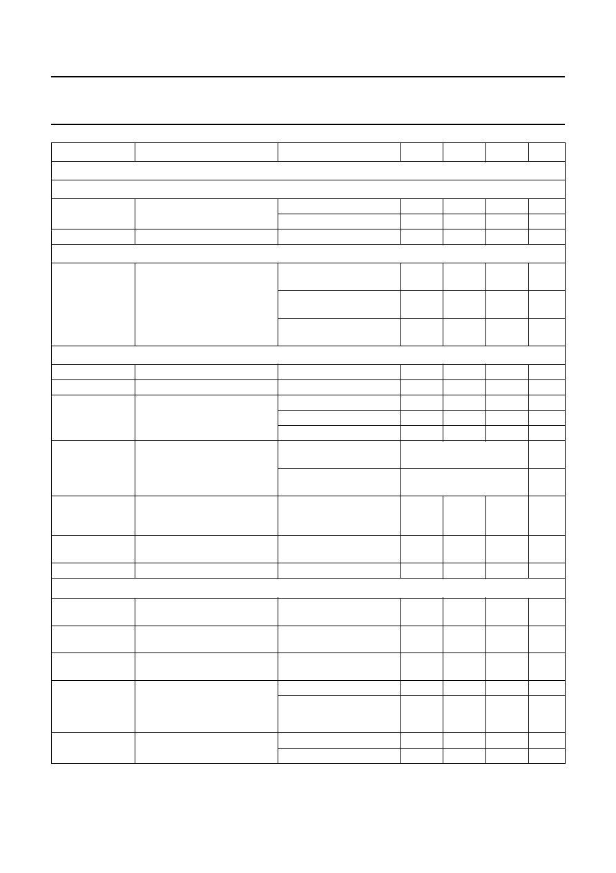
Output stage for line driver pulses: pin HDRV
OPEN-COLLECTOR OUTPUT STAGE
Vsat(HDRV)
saturation voltage
IHDRV =20mA
0.3
V
IHDRV =60mA
0.8
V
ILO(HDRV)
output leakage current
VHDRV =16V
10
A
AUTOMATIC VARIATION OF DUTY CYCLE
tHDRV(OFF)/tH
relative tOFF time of HDRV
output; measured at
VHDRV = 3 V; HDRV duty cycle
is modulated by the relation
IHREF/IVREF
IHDRV = 20 mA;
fH = 31.45 kHz; see Fig.16
42
45
48
%
IHDRV = 20 mA;
fH = 58 kHz; see Fig.16
45.5
48.5
51.5
%
IHDRV = 20 mA;
fH = 110 kHz; see Fig.16
49
52
55
%
X-ray protection: pins XRAY and XSEL
VXRAY(sl)
slicing voltage level for latch
6.22
6.39
6.56
V
tW(XRAY)(min)
minimum width of trigger pulse
30
s
Ri(XRAY)
input resistance at pin 2
VXRAY <6.38V+VBE
500
k
VXRAY >6.38V+VBE
5
k
standby mode
5
k
XRAYrst
reset of X-ray latch
pin 9 open-circuit or
connected to GND
set control bit SOFTST via
the I2C-bus
pin 9 connected to VCC via
RXSEL
switch off VCC then re-apply
VCC
VCC(XRAY)(min)
minimum supply voltage for
correct function of the X-ray
latch
pin 9 connected to VCC via
RXSEL
4V
VCC(XRAY)(max)
maximum supply voltage for
reset of the X-ray latch
pin 9 connected to VCC via
RXSEL
2
V
RXSEL
external resistor at pin 9
no reset via I2C-bus
56
130
k
Vertical oscillator [oscillator frequency in application without adjustment of free-running frequency ffr(V)]
ffr(V)
free-running frequency
RVREF =22k;
CVCAP = 100 nF
40
42
43.3
Hz
fcr(V)
vertical frequency catching
range
constant amplitude; note 7 50
160
Hz
VVREF
voltage at reference input for
vertical oscillator
3.0
V
td(scan)
delay between trigger pulse
and start of ramp at VCAP
(pin 24) (width of vertical
blanking pulse)
control bit VBLK = 0
220
260
300
s
control bit VBLK = 1
305
350
395
s
IVAGC
amplitude control current
control bit AGCDIS = 0
±120
±200
±300
A
control bit AGCDIS = 1
0
A
SYMBOL
PARAMETER
CONDITIONS
MIN.
TYP.
MAX.
UNIT
相關(guān)PDF資料 |
PDF描述 |
|---|---|
| 935260802112 | HORIZ/VERT DEFLECTION IC, PDIP32 |
| 935260845118 | PLL FREQUENCY SYNTHESIZER, 2200 MHz, PDSO16 |
| 935260845112 | PLL FREQUENCY SYNTHESIZER, 2200 MHz, PDSO16 |
| 935260937112 | SPECIALTY CONSUMER CIRCUIT, PDSO28 |
| 935260937118 | SPECIALTY CONSUMER CIRCUIT, PDSO28 |
相關(guān)代理商/技術(shù)參數(shù) |
參數(shù)描述 |
|---|---|
| 935241-0001 | 制造商: 功能描述: 制造商:DIGITRAN 功能描述: 制造商:undefined 功能描述: |
| 935241-1 | 制造商:DIGITRAN 功能描述: 制造商:DTRAN 功能描述: |
| 935245650125 | 制造商:NXP Semiconductors 功能描述:Inverter 1-Element CMOS 5-Pin TSSOP T/R |
| 935248-90 | 制造商:JANCO 功能描述:935248-90 |
| 9-3525-012 | 制造商:KEYSTONE 功能描述:MODIFIED 3525,VERSION E |
發(fā)布緊急采購,3分鐘左右您將得到回復(fù)。