- 您現(xiàn)在的位置:買賣IC網 > PDF目錄24799 > 935255770512 (NXP SEMICONDUCTORS) 8-BIT, 16 MHz, MICROCONTROLLER, PQCC44 PDF資料下載
參數(shù)資料
| 型號: | 935255770512 |
| 廠商: | NXP SEMICONDUCTORS |
| 元件分類: | 微控制器/微處理器 |
| 英文描述: | 8-BIT, 16 MHz, MICROCONTROLLER, PQCC44 |
| 封裝: | PLASTIC, MO-047, SOT-187-2, LCC-44 |
| 文件頁數(shù): | 9/35頁 |
| 文件大小: | 313K |
| 代理商: | 935255770512 |
第1頁第2頁第3頁第4頁第5頁第6頁第7頁第8頁當前第9頁第10頁第11頁第12頁第13頁第14頁第15頁第16頁第17頁第18頁第19頁第20頁第21頁第22頁第23頁第24頁第25頁第26頁第27頁第28頁第29頁第30頁第31頁第32頁第33頁第34頁第35頁
Philips Semiconductors
Product specification
80C31/80C32
80C51 8-bit microcontroller family
128/256 byte RAM ROMless low voltage (2.7V–5.5V),
low power, high speed (33 MHz)
2000 Aug 07
17
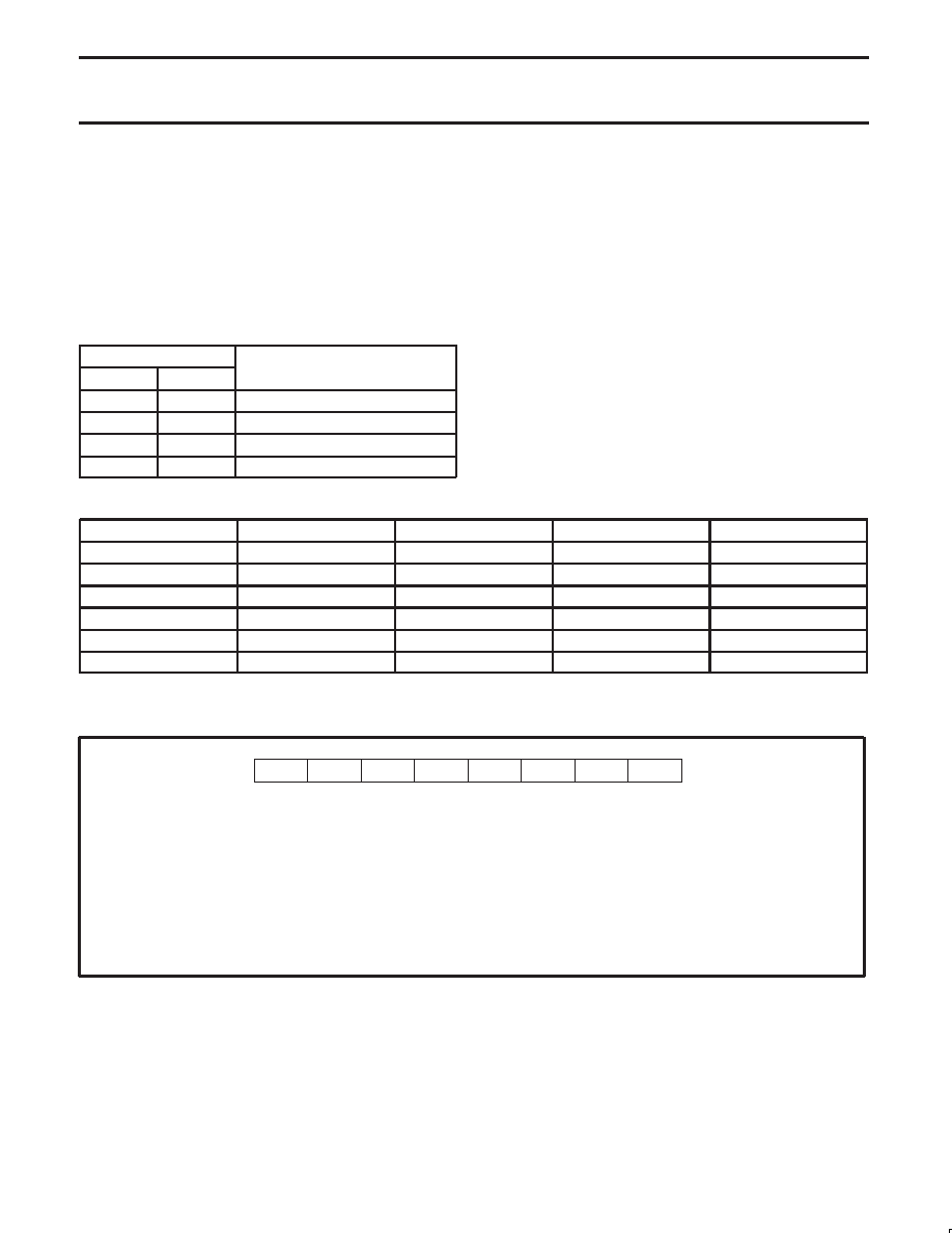
Interrupt Priority Structure
The 80C31 and 80C32 have a 6-source four-level interrupt
structure. They are the IE, IP and IPH. (See Figures 10, 11, and 12.)
The IPH (Interrupt Priority High) register that makes the four-level
interrupt structure possible. The IPH is located at SFR address B7H.
The structure of the IPH register and a description of its bits is
shown in Figure 12.
The function of the IPH SFR is simple and when combined with the
IP SFR determines the priority of each interrupt. The priority of each
interrupt is determined as shown in the following table:
PRIORITY BITS
INTERRUPT PRIORITY LEVEL
IPH.x
IP.x
INTERRUPT PRIORITY LEVEL
0
Level 0 (lowest priority)
0
1
Level 1
1
0
Level 2
1
Level 3 (highest priority)
An interrupt will be serviced as long as an interrupt of equal or
higher priority is not already being serviced. If an interrupt of equal
or higher level priority is being serviced, the new interrupt will wait
until it is finished before being serviced. If a lower priority level
interrupt is being serviced, it will be stopped and the new interrupt
serviced. When the new interrupt is finished, the lower priority level
interrupt that was stopped will be completed.
Table 7.
Interrupt Table
SOURCE
POLLING PRIORITY
REQUEST BITS
HARDWARE CLEAR?
VECTOR ADDRESS
X0
1
IE0
N (L)1
Y (T)2
03H
T0
2
TP0
Y
0BH
X1
3
IE1
N (L)
Y (T)
13H
T1
4
TF1
Y
1BH
SP
5
RI, TI
N
23H
T2
6
TF2, EXF2
N
2BH
NOTES:
1. L = Level activated
2. T = Transition activated
EX0
IE (0A8H)
Enable Bit = 1 enables the interrupt.
Enable Bit = 0 disables it.
BIT
SYMBOL
FUNCTION
IE.7
EA
Global disable bit. If EA = 0, all interrupts are disabled. If EA = 1, each interrupt can be individually
enabled or disabled by setting or clearing its enable bit.
IE.6
—
Not implemented. Reserved for future use.
IE.5
ET2
Timer 2 interrupt enable bit.
IE.4
ES
Serial Port interrupt enable bit.
IE.3
ET1
Timer 1 interrupt enable bit.
IE.2
EX1
External interrupt 1 enable bit.
IE.1
ET0
Timer 0 interrupt enable bit.
IE.0
EX0
External interrupt 0 enable bit.
SU00571
ET0
EX1
ET1
ES
ET2
—
EA
0
1
2
3
4
5
6
7
Figure 10. IE Registers
相關PDF資料 |
PDF描述 |
|---|---|
| 935255910112 | 8-BIT, 33 MHz, MICROCONTROLLER, PDIP40 |
| 935260357512 | 8-BIT, 33 MHz, MICROCONTROLLER, PQCC44 |
| 935255920112 | 8-BIT, 33 MHz, MICROCONTROLLER, PDIP40 |
| 935255560512 | 8-BIT, 16 MHz, MICROCONTROLLER, PQCC44 |
| 07105GOA | Circular Connector; No. of Contacts:41; Series:; Body Material:Aluminum; Connecting Termination:Solder; Connector Shell Size:22; Circular Contact Gender:Pin; Circular Shell Style:Jam Nut Receptacle; Insert Arrangement:22-41 |
相關代理商/技術參數(shù) |
參數(shù)描述 |
|---|---|
| 935257650112 | 制造商:NXP Semiconductors 功能描述:SUB ONLY ICSUBS TO 935257650112 |
| 935260093112 | 制造商:NXP Semiconductors 功能描述:IC AVIC ADV BASESTATION 14SOIC |
| 935261069122 | 制造商:NXP Semiconductors 功能描述:IC SECURITY TRANSPONDER PLLMC |
| 935262025112 | 制造商:NXP Semiconductors 功能描述:SUB ONLY IC |
| 935262217118 | 制造商:NXP Semiconductors 功能描述:Real Time Clock Serial 8-Pin SO T/R |
發(fā)布緊急采購,3分鐘左右您將得到回復。