- 您現(xiàn)在的位置:買(mǎi)賣(mài)IC網(wǎng) > PDF目錄24800 > 935260608118 (NXP SEMICONDUCTORS) TELEPHONE MULTIFUNCTION CKT, PDSO28 PDF資料下載
參數(shù)資料
| 型號(hào): | 935260608118 |
| 廠商: | NXP SEMICONDUCTORS |
| 元件分類: | 無(wú)繩電話/電話 |
| 英文描述: | TELEPHONE MULTIFUNCTION CKT, PDSO28 |
| 封裝: | PLASTIC, SOT-136, SO-28 |
| 文件頁(yè)數(shù): | 14/56頁(yè) |
| 文件大?。?/td> | 360K |
| 代理商: | 935260608118 |
第1頁(yè)第2頁(yè)第3頁(yè)第4頁(yè)第5頁(yè)第6頁(yè)第7頁(yè)第8頁(yè)第9頁(yè)第10頁(yè)第11頁(yè)第12頁(yè)第13頁(yè)當(dāng)前第14頁(yè)第15頁(yè)第16頁(yè)第17頁(yè)第18頁(yè)第19頁(yè)第20頁(yè)第21頁(yè)第22頁(yè)第23頁(yè)第24頁(yè)第25頁(yè)第26頁(yè)第27頁(yè)第28頁(yè)第29頁(yè)第30頁(yè)第31頁(yè)第32頁(yè)第33頁(yè)第34頁(yè)第35頁(yè)第36頁(yè)第37頁(yè)第38頁(yè)第39頁(yè)第40頁(yè)第41頁(yè)第42頁(yè)第43頁(yè)第44頁(yè)第45頁(yè)第46頁(yè)第47頁(yè)第48頁(yè)第49頁(yè)第50頁(yè)第51頁(yè)第52頁(yè)第53頁(yè)第54頁(yè)第55頁(yè)第56頁(yè)
2000 May 19
21
Philips Semiconductors
Product specication
One-chip telephone ICs with speech,
dialler and ringer functions
UBA2050(A); UBA2051(A;C)
TONE DIALLER (PINS MDY/TONE AND LED)
The digits are transmitted as two simultaneously
generated tones: the Dual-Tone Multi-Frequency (DTMF)
system. These dual tones which are provided at the
MDY/TONE output are internally generated with two digital
sine wave synthesizers together with digital-to-analog
converters. Their amplitudes are precisely scaled
according to a band gap voltage reference. This ensures
tone output levels independent of the supply voltage and
temperature. The two sine waves are summed and then
filtered by an on-chip switched capacitor filter, followed by
an active RC low-pass filter. These guarantee that all
DTMF tones generated fulfil the CEPT CS203
recommendations with respect to amplitude, frequency
deviation, total harmonic distortion and suppression of
unwanted frequency components. Tone digits are
separated by a pause time (tp).
At dialling, the DTMF input of the transmission part is
enabled while the microphone and receive amplifier inputs
are disabled. The signal at the DTMF input is sent to the
receive output at a low level [see Section “DTMF
amplification (pin DTMF)”].
Valid keys are the digits [0] to [9], [
/T], [#], [R], [LNR/P]
and [P
→ T].
The dialling mode, the flash time and the access pause
time depend on the resistor options: PTS, FTSA, FTSB
and APT (see Fig.25 and Table 7).
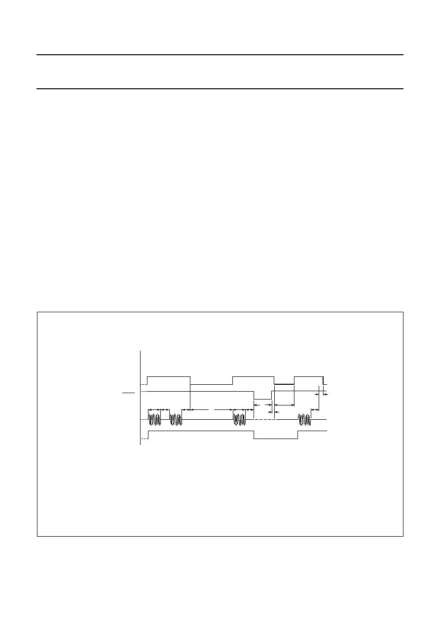
Figure 22 shows the timing diagram in tone dialling mode
when keys [3], [3], [LNR/P], [4], [R] and [2] are pressed.
In DTMF dialling mode, pin LED of the UBA205xA is set
LOW after the hook-switch changes to off-hook and
becomes HIGH as soon as a key is pressed and the first
DTMF code is sent. Pin LED is a push-pull output and is
LOW when VDD <VPOR.
The DTMF standard frequencies are implemented as
shown in Table 4.
handbook, full pagewidth
MGU141
DP/FL
KEYS
internal
MUTE
MDY/TONE
LED
(1)
high impedance
.....[3] ......[3] ..............[LNR/P] .......................[4].............. [R]....................... [2]
tfho
tfl
tt
tp
tt
tp
tap
tifp
tmho
Fig.22 Timing diagram in tone dialling mode.
tt = burst time.
tp = pause time.
tap = access pause time.
tfl = flash time.
tifp = interflash pause time.
tmho = mute holdover time.
tfho = flash holdover time.
Note: the maximum tone burst and pause times are equal to the real key press/release time.
(1) pin LED only available inUBA205xA.
相關(guān)PDF資料 |
PDF描述 |
|---|---|
| 935260687112 | TELEPHONE MULTIFUNCTION CKT, PDSO28 |
| 935260687118 | TELEPHONE MULTIFUNCTION CKT, PDSO28 |
| 935260607112 | TELEPHONE MULTIFUNCTION CKT, PDSO28 |
| 935260607118 | TELEPHONE MULTIFUNCTION CKT, PDSO28 |
| 935260690112 | TELEPHONE MULTIFUNCTION CKT, PDSO28 |
相關(guān)代理商/技術(shù)參數(shù) |
參數(shù)描述 |
|---|---|
| 935261069122 | 制造商:NXP Semiconductors 功能描述:IC SECURITY TRANSPONDER PLLMC |
| 935262025112 | 制造商:NXP Semiconductors 功能描述:SUB ONLY IC |
| 935262217118 | 制造商:NXP Semiconductors 功能描述:Real Time Clock Serial 8-Pin SO T/R |
| 935264217557 | 制造商:NXP Semiconductors 功能描述:SUB ONLY IC |
| 935267356112 | 制造商:NXP Semiconductors 功能描述:IC TEA1507PN |
發(fā)布緊急采購(gòu),3分鐘左右您將得到回復(fù)。