- 您現(xiàn)在的位置:買賣IC網(wǎng) > PDF目錄24804 > 935262575512 (NXP SEMICONDUCTORS) 8-BIT, FLASH, 33 MHz, MICROCONTROLLER, PQCC44 PDF資料下載
參數(shù)資料
| 型號: | 935262575512 |
| 廠商: | NXP SEMICONDUCTORS |
| 元件分類: | 微控制器/微處理器 |
| 英文描述: | 8-BIT, FLASH, 33 MHz, MICROCONTROLLER, PQCC44 |
| 封裝: | PLASTIC, LCC-44 |
| 文件頁數(shù): | 4/35頁 |
| 文件大小: | 250K |
| 代理商: | 935262575512 |
第1頁第2頁第3頁當前第4頁第5頁第6頁第7頁第8頁第9頁第10頁第11頁第12頁第13頁第14頁第15頁第16頁第17頁第18頁第19頁第20頁第21頁第22頁第23頁第24頁第25頁第26頁第27頁第28頁第29頁第30頁第31頁第32頁第33頁第34頁第35頁

Philips Semiconductors
Product specification
89C51/89C52/89C54/89C58
80C51 8-bit microcontroller family
4K/8K/16K/32K Flash
1999 Oct 27
12
OSC
÷ 2
C/T2 = 0
C/T2 = 1
TR2
Control
TL2
(8-bits)
TH2
(8-bits)
÷ 16
RCAP2L
RCAP2H
EXEN2
Control
EXF2
Timer 2
Interrupt
T2EX Pin
Transition
Detector
T2 Pin
Reload
NOTE: OSC. Freq. is divided by 2, not 12.
÷ 2
“0”
“1”
RX Clock
÷ 16
TX Clock
“0”
“1”
“0”
“1”
Timer 1
Overflow
Note availability of additional external interrupt.
SMOD
RCLK
TCLK
SU00068
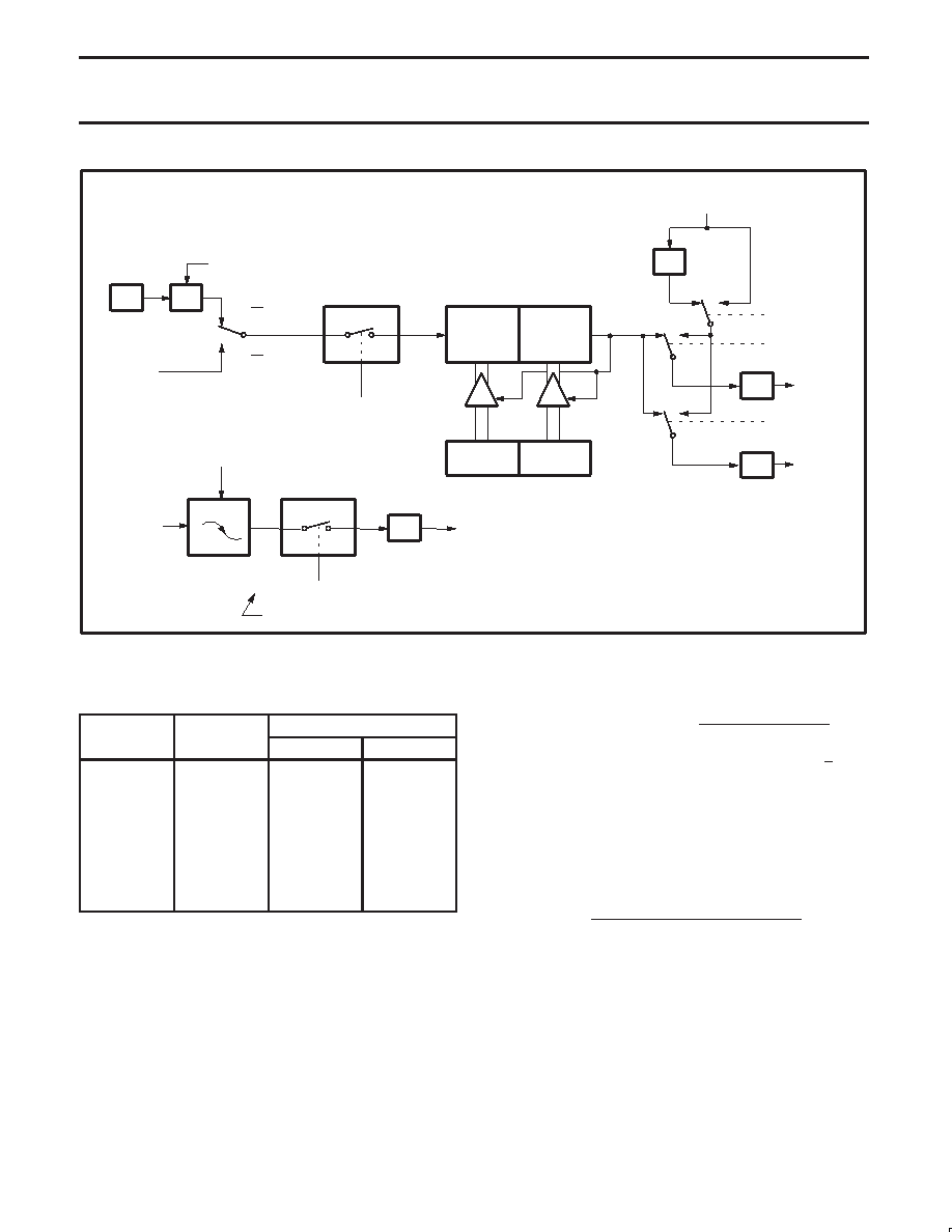
Figure 6. Timer 2 in Baud Rate Generator Mode
Table 4.
Timer 2 Generated Commonly Used
Baud Rates
Ba d Rate
Osc Freq
Timer 2
Baud Rate
Osc Freq
RCAP2H
RCAP2L
375 k
12 MHz
FF
9.6 k
12 MHz
FF
D9
2.8 k
12 MHz
FF
B2
2.4 k
12 MHz
FF
64
1.2 k
12 MHz
FE
C8
300
12 MHz
FB
1E
110
12 MHz
F2
AF
300
6 MHz
FD
8F
110
6 MHz
F9
57
Baud Rate Generator Mode
Bits TCLK and/or RCLK in T2CON (Table 4) allow the serial port
transmit and receive baud rates to be derived from either Timer 1 or
Timer 2. When TCLK= 0, Timer 1 is used as the serial port transmit
baud rate generator. When TCLK= 1, Timer 2 is used as the serial
port transmit baud rate generator. RCLK has the same effect for the
serial port receive baud rate. With these two bits, the serial port can
have different receive and transmit baud rates – one generated by
Timer 1, the other by Timer 2.
Figure 6 shows the Timer 2 in baud rate generation mode. The baud
rate generation mode is like the auto-reload mode, in that a rollover in
TH2 causes the Timer 2 registers to be reloaded with the 16-bit value
in registers RCAP2H and RCAP2L, which are preset by software.
The baud rates in modes 1 and 3 are determined by Timer 2’s
overflow rate given below:
Modes 1 and 3 Baud Rates
+ Timer 2 Overflow Rate
16
The timer can be configured for either “timer” or “counter” operation.
In many applications, it is configured for “timer” operation (C/T2*=0).
Timer operation is different for Timer 2 when it is being used as a
baud rate generator.
Usually, as a timer it would increment every machine cycle (i.e., 1/12
the oscillator frequency). As a baud rate generator, it increments
every state time (i.e., 1/2 the oscillator frequency). Thus the baud
rate formula is as follows:
Oscillator Frequency
[32
[65536
* (RCAP2H, RCAP2L)]]
Modes 1 and 3 Baud Rates =
Where:
(RCAP2H, RCAP2L) = The content of RCAP2H and
RCAP2L taken as a 16-bit unsigned integer.
The Timer 2 as a baud rate generator mode shown in Figure 6, is
valid only if RCLK and/or TCLK = 1 in T2CON register. Note that a
rollover in TH2 does not set TF2, and will not generate an interrupt.
Thus, the Timer 2 interrupt does not have to be disabled when
Timer 2 is in the baud rate generator mode. Also if the EXEN2
(T2 external enable flag) is set, a 1-to-0 transition in T2EX
(Timer/counter 2 trigger input) will set EXF2 (T2 external flag) but
will not cause a reload from (RCAP2H, RCAP2L) to (TH2,TL2).
Therefore when Timer 2 is in use as a baud rate generator, T2EX
can be used as an additional external interrupt, if needed.
相關(guān)PDF資料 |
PDF描述 |
|---|---|
| 935262602512 | 8-BIT, FLASH, 33 MHz, MICROCONTROLLER, PQCC44 |
| 935262574512 | 8-BIT, FLASH, 33 MHz, MICROCONTROLLER, PQCC44 |
| 935262606112 | 8-BIT, FLASH, 33 MHz, MICROCONTROLLER, PDIP40 |
| 935262611557 | 8-BIT, FLASH, 33 MHz, MICROCONTROLLER, PQFP44 |
| 935262572112 | 8-BIT, FLASH, 33 MHz, MICROCONTROLLER, PDIP40 |
相關(guān)代理商/技術(shù)參數(shù) |
參數(shù)描述 |
|---|---|
| 935264217557 | 制造商:NXP Semiconductors 功能描述:SUB ONLY IC |
| 935267356112 | 制造商:NXP Semiconductors 功能描述:IC TEA1507PN |
| 935268081112 | 制造商:NXP Semiconductors 功能描述:SUB ONLY IC |
| 935268721125 | 制造商:NXP Semiconductors 功能描述:Buffer/Line Driver 1-CH Non-Inverting 3-ST CMOS 5-Pin TSSOP T/R |
| 935269304128 | 制造商:ST-Ericsson 功能描述:IC AUDIO CODEC W/TCH SCRN 48LQFP |
發(fā)布緊急采購,3分鐘左右您將得到回復。