- 您現(xiàn)在的位置:買賣IC網(wǎng) > PDF目錄24826 > 935267419557 (NXP SEMICONDUCTORS) 1 CHANNEL(S), 1M bps, SERIAL COMM CONTROLLER, PQFP44 PDF資料下載
參數(shù)資料
| 型號: | 935267419557 |
| 廠商: | NXP SEMICONDUCTORS |
| 元件分類: | 微控制器/微處理器 |
| 英文描述: | 1 CHANNEL(S), 1M bps, SERIAL COMM CONTROLLER, PQFP44 |
| 封裝: | 10 X 10 MM, 1.75 MM HEIGHT, PLASTIC, SOT-307-2, QFP-44 |
| 文件頁數(shù): | 14/42頁 |
| 文件大小: | 249K |
| 代理商: | 935267419557 |
第1頁第2頁第3頁第4頁第5頁第6頁第7頁第8頁第9頁第10頁第11頁第12頁第13頁當前第14頁第15頁第16頁第17頁第18頁第19頁第20頁第21頁第22頁第23頁第24頁第25頁第26頁第27頁第28頁第29頁第30頁第31頁第32頁第33頁第34頁第35頁第36頁第37頁第38頁第39頁第40頁第41頁第42頁

Philips Semiconductors
Product specification
SC28L91
3.3V–5.0V Universal Asynchronous
Receiver/Transmitter (UART)
2000 Sep 22
21
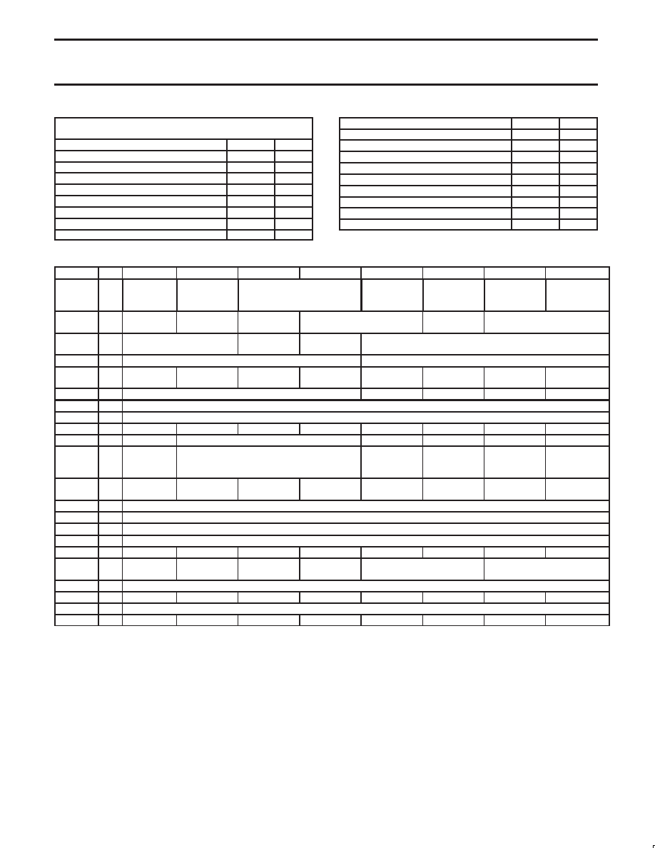
Register Acronyms and Read / Write Capability
(R/W = Read/Write, R = Read only, W = Write only)
Mode Register
MRn
R/W
Status Register
SR
R
Clock Select
CSR
W
Command Register
CR
W
Receiver FIFO
RxFIFO
R
Transmitter FIFO
RxFIFO
W
Input Port Change Register
IPCR
R
Auxiliary Control Register
ACR
W
Interrupt Status Register
ISR
R
Interrupt Mask Register
IMR
W
Counter Timer Upper Value
CTU
R
Counter Timer Lower Value
CTL
R
Counter Timer Preset Upper
CTPU
W
Counter Timer Preset Lower
CTPL
W
Input Port Register
IPR
R
Output Configuration Register
OPCR
W
Set Output Port
Bits
W
Reset Output Port
Bits
W
Interrupt vector or GP register
IVR/GP
R/W
Table 2. Condensed Register bit formats
N
ame
Adr
Bit 7
Bit 6
Bit 5
Bit 4
Bit 3
Bit 2
Bit 1
Bit 0
MR0
0
WATCH
DOG
RxINT BIT 2
TxINT [1:0]
FIFO SIZE
BAUD RATE
EXTENDED
II
TEST 2
BAUD RATE
EXTENDED 1
MR1
0
RxRTS
Control
RxINT BIT 1
Error Mode
Parity Mode
Parity Type
Bits per Character
MR2
0
Channel Mode
TxRTS Con-
trol
CTSN Enable
Tx
Stop Bit Length
CSR
1
Receiver Clock, Select Code
Transmitter Clock select code,
SR
1
Received
Break
Framing Er-
ror
Parity Error
Overrun Error
TxEMT
TxRDY
RxFULL
RxRDY
CR
2
Channel Command codes
Disable Tx
Enable Tx
Disable Rx
Enable Rx
RxFIFO
3
Read 8 bits from Rx FIFO
TxFIFO
3
Write 8 bits to Tx FIFO
IPCR
4
Delta IP3
Delta IP2
Delta IP1
Delta IP0
State of IP3
State of IP2
State of IP1
State of IP0
ACR
4
Baud Group
Counter Timer mode and clock select
Enable IP3
Enable IP2
Enable IP1
Enable IP0
ISR
5
Change In-
put Port
Ignore in ISR Reads
Counter
Ready
Change
Break
RxRDY
TxRDY
IMR
5
Change In-
put Port
Set to 0
Counter
Ready
Change
Break
RxRDY
TxRDY
CTU
6
Read 8 MSb of the BRG Timer divisor.
CTPU
6
Write 8 MSb of the BRG Timer divisor.
CTL
7
Read 8 LSb of the BRG Timer divisor.
CTPL
7
Write 8 LSb of the BRG Timer divisor.
IPR
D
State of IP
State of IP 6
State of IP 5
State of IP 4
State of IP 3
State of IP 2
State of IP1
State of IP 0
OPCR
D
Configure
OP7
Configure
OP6
Configure
OP5
Configure
OP4
Configure OP3
Configure OP2
Strt C/T
E
Read Address E to start Counter Timer
SOPR
E
Set OP 7
Set OP 6
Set OP 5
Set OP 4
Set OP 3
Set OP 2
Set OP 1
Set OP 0
Stp C/T
F
Read Address F to stop counter Timer
ROPR
F
Reset OP 7
Reset OP 6
Reset OP 5
Reset OP 4
Reset OP 3
Reset OP 2
Reset OP 1
Reset OP 0
相關PDF資料 |
PDF描述 |
|---|---|
| 08-M150-KIT-FEC | IMPACT PRINTER KIT |
| 08-M160-KIT-FEC | IMPACT PRINTER KIT |
| 935267473115 | AHC SERIES, 1-INPUT INVERT GATE, PDSO5 |
| 935267473118 | AHC SERIES, 1-INPUT INVERT GATE, PDSO5 |
| 935267474115 | AHCT/VHCT SERIES, 1-INPUT INVERT GATE, PDSO5 |
相關代理商/技術參數(shù) |
參數(shù)描述 |
|---|---|
| 935268081112 | 制造商:NXP Semiconductors 功能描述:SUB ONLY IC |
| 935268721125 | 制造商:NXP Semiconductors 功能描述:Buffer/Line Driver 1-CH Non-Inverting 3-ST CMOS 5-Pin TSSOP T/R |
| 935269304128 | 制造商:ST-Ericsson 功能描述:IC AUDIO CODEC W/TCH SCRN 48LQFP |
| 935269544557 | 制造商:NXP Semiconductors 功能描述:SUB ONLY TDA9587-2US1-V1.3 |
| 935269987557 | 制造商:NXP Semiconductors 功能描述:SUB ONLY TDA9587-1US1-V1.8 SUBBED TO 935269987557 |
發(fā)布緊急采購,3分鐘左右您將得到回復。