- 您現(xiàn)在的位置:買賣IC網(wǎng) > PDF目錄4377 > A1240A-TQ176C (Microsemi SoC)IC FPGA 4K GATES 176-TQFP COM PDF資料下載
參數(shù)資料
| 型號: | A1240A-TQ176C |
| 廠商: | Microsemi SoC |
| 文件頁數(shù): | 14/54頁 |
| 文件大?。?/td> | 0K |
| 描述: | IC FPGA 4K GATES 176-TQFP COM |
| 標(biāo)準(zhǔn)包裝: | 40 |
| 系列: | ACT™ 2 |
| LAB/CLB數(shù): | 684 |
| 輸入/輸出數(shù): | 104 |
| 門數(shù): | 4000 |
| 電源電壓: | 4.5 V ~ 5.5 V |
| 安裝類型: | 表面貼裝 |
| 工作溫度: | 0°C ~ 70°C |
| 封裝/外殼: | 176-LQFP |
| 供應(yīng)商設(shè)備封裝: | 176-TQFP(24x24) |
第1頁第2頁第3頁第4頁第5頁第6頁第7頁第8頁第9頁第10頁第11頁第12頁第13頁當(dāng)前第14頁第15頁第16頁第17頁第18頁第19頁第20頁第21頁第22頁第23頁第24頁第25頁第26頁第27頁第28頁第29頁第30頁第31頁第32頁第33頁第34頁第35頁第36頁第37頁第38頁第39頁第40頁第41頁第42頁第43頁第44頁第45頁第46頁第47頁第48頁第49頁第50頁第51頁第52頁第53頁第54頁

ACT 2 Family FPGAs
R e visio n 8
2 - 15
A1240A Timing Characteristics
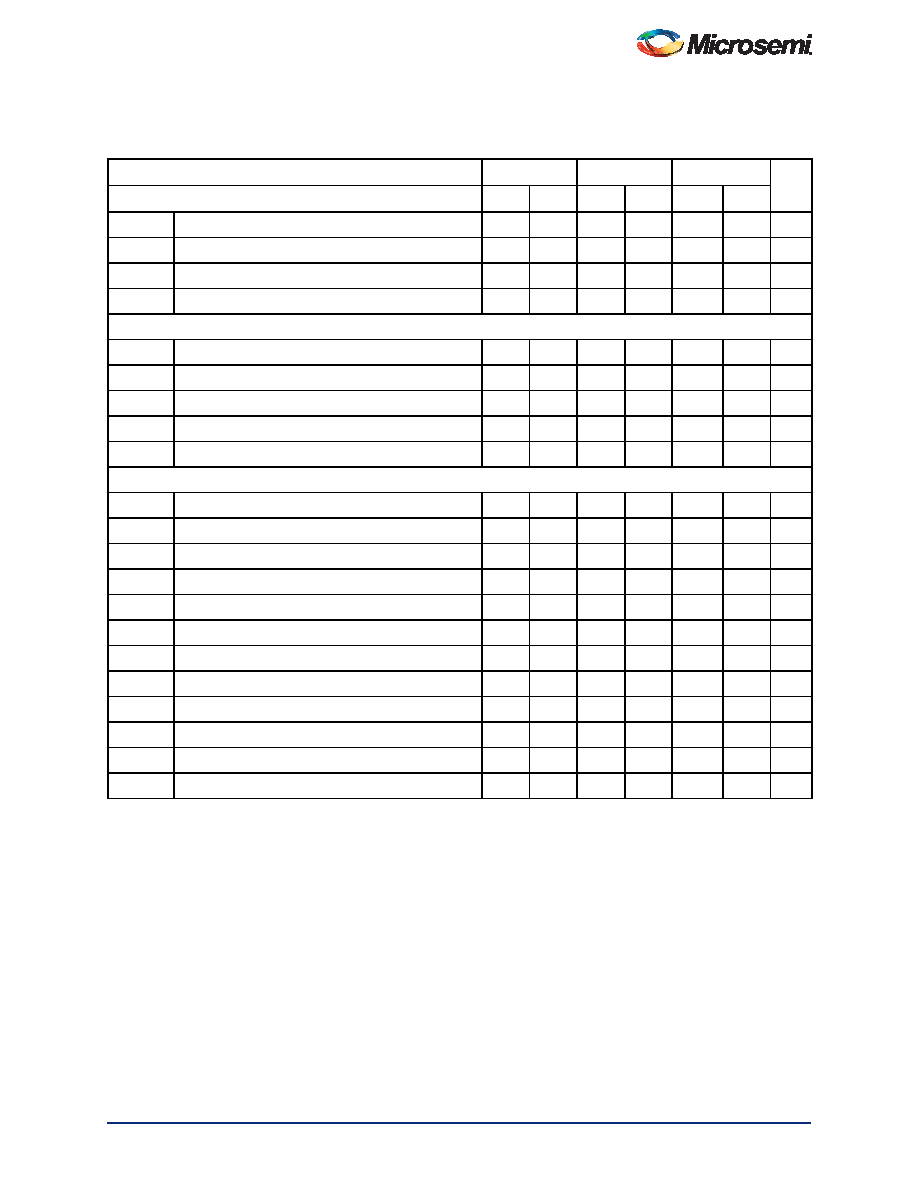
Table 2-15 A1240A Worst-Case Commercial Conditions, VCC = 4.75 V, TJ = 70°C
Logic Module Propagation Delays1
–2 Speed3
–1 Speed
Std. Speed
Units
Parameter/Description
Min.
Max.
Min.
Max.
Min.
Max.
tPD1
Single Module
3.8
4.3
5.0
ns
tCO
Sequential Clock to Q
3.8
4.3
5.0
ns
tGO
Latch G to Q
3.8
4.3
5.0
ns
tRS
Flip-Flop (Latch) Reset to Q
3.8
4.3
5.0
ns
Predicted Routing Delays2
tRD1
FO = 1 Routing Delay
1.4
1.5
1.8
ns
tRD2
FO = 2 Routing Delay
1.7
2.0
2.3
ns
tRD3
FO = 3 Routing Delay
2.3
2.6
3.0
ns
tRD4
FO = 4 Routing Delay
3.1
3.5
4.1
ns
tRD8
FO = 8 Routing Delay
4.7
5.4
6.3
ns
Sequential Timing Characteristics3,4
tSUD
Flip-Flop (Latch) Data Input Setup
0.4
0.5
ns
tHD
Flip-Flop (Latch) Data Input Hold
0.0
ns
tSUENA
Flip-Flop (Latch) Enable Setup
0.8
0.9
1.0
ns
tHENA
Flip-Flop (Latch) Enable Hold
0.0
ns
tWCLKA
Flip-Flop (Latch) Clock Active Pulse Width
4.5
6.0
6.5
ns
tWASYN
Flip-Flop (Latch) Clock Asynchronous Pulse Width
4.5
6.0
6.5
ns
tA
Flip-Flop Clock Input Period
9.8
12.0
15.0
ns
tINH
Input Buffer Latch Hold
0.0
ns
tINSU
Input Buffer Latch Setup
0.4
0.5
ns
tOUTH
Output Buffer Latch Hold
0.0
ns
tOUTSU
Output Buffer Latch Setup
0.4
0.5
ns
fMAX
Flip-Flop (Latch) Clock Frequency
100.0
80.0
66.0
MHz
Notes:
1. For dual-module macros, use tPD1 + tRD1 + tPDn, tCO + tRD1 + tPDn, or tPD1 + tRD1 + tSUD —whichever is appropriate.
2. Routing delays are for typical designs across worst-case operating conditions. These parameters should be used for
estimating device performance. Post-route timing analysis or simulation is required to determine actual worst-case
performance. Post-route timing is based on actual routing delay measurements performed on the device prior to
shipment.
3. Data applies to macros based on the S-module. Timing parameters for sequential macros constructed from C-modules
can be obtained from the DirectTime Analyzer utility.
4. Setup and hold timing parameters for the Input Buffer Latch are defined with respect to the PAD and the D input. External
setup/hold timing parameters must account for delay from an external PAD signal to the G inputs. Delay from an external
PAD signal to the G input subtracts (adds) to the internal setup (hold) time.
相關(guān)PDF資料 |
PDF描述 |
|---|---|
| A1240A-TQG176C | IC FPGA 4K GATES 176-TQFP COM |
| AX1000-1BGG729I | IC FPGA AXCELERATOR 1M 729-PBGA |
| AX1000-1BG729I | IC FPGA AXCELERATOR 1M 729-PBGA |
| EP1S10F484I6N | IC STRATIX FPGA 10K LE 484-FBGA |
| EP1S10F484C5N | IC STRATIX FPGA 10K LE 484-FBGA |
相關(guān)代理商/技術(shù)參數(shù) |
參數(shù)描述 |
|---|---|
| A1240A-TQ176I | 制造商:MICROSEMI 制造商全稱:Microsemi Corporation 功能描述:ACT 2 Family FPGAs |
| A1240A-TQ176M | 制造商:MICROSEMI 制造商全稱:Microsemi Corporation 功能描述:ACT 2 Family FPGAs |
| A1240A-TQG160B | 制造商:MICROSEMI 制造商全稱:Microsemi Corporation 功能描述:ACT 2 Family FPGAs |
| A1240A-TQG160C | 制造商:MICROSEMI 制造商全稱:Microsemi Corporation 功能描述:ACT 2 Family FPGAs |
| A1240A-TQG160I | 制造商:MICROSEMI 制造商全稱:Microsemi Corporation 功能描述:ACT 2 Family FPGAs |
發(fā)布緊急采購,3分鐘左右您將得到回復(fù)。