- 您現(xiàn)在的位置:買賣IC網(wǎng) > PDF目錄362016 > A371-22ND KPT 12C 8#20 4#16 PIN PLUG PDF資料下載
參數(shù)資料
| 型號: | A371-22ND |
| 英文描述: | KPT 12C 8#20 4#16 PIN PLUG |
| 中文描述: | A371型模擬制冷隔離足協(xié)FastLight⑩激光模組 |
| 文件頁數(shù): | 4/8頁 |
| 文件大?。?/td> | 168K |
| 代理商: | A371-22ND |
A371-Type Analog Uncooled Isolated
DFB
FastLight
Laser Module
Data Sheet
January 1999
4
Lucent Technologies Inc.
Electro/Optical Characteristics
(continued)
Analog Operation
The A371-Type Laser Module has the capability of being used in a wide variety of analog operations. These may
include several channels of pure video signals, or a mix of video signals with digital data channels riding on analog
carriers. It is difficult to prepare a single battery of testing conditions that will satisfy all applications. The following
table contains a set of testing conditions that Lucent believes will give a broad indication of the performance of the
A371 Series Laser Module. Please contact your local Field Application Engineer if different testing conditions and
parametric limits are required.
The distortion characteristics are measured using a two-tone test. The frequencies are 13 MHz and 19 MHz. The
second-order distortion components are measured at f1 + f2 = 32 MHz and f1 – f2 = 6 MHz. All third-order distor-
tion components are measured in the frequency range of 5 MHz—200 MHz, and they meet the required level. All
measurements are made with SC-SPC connectors on the laser module pigtails.
* See Table 5 for more information.
Double-isolated version.
Low-performance option.
§Single- and double-isolated versions.
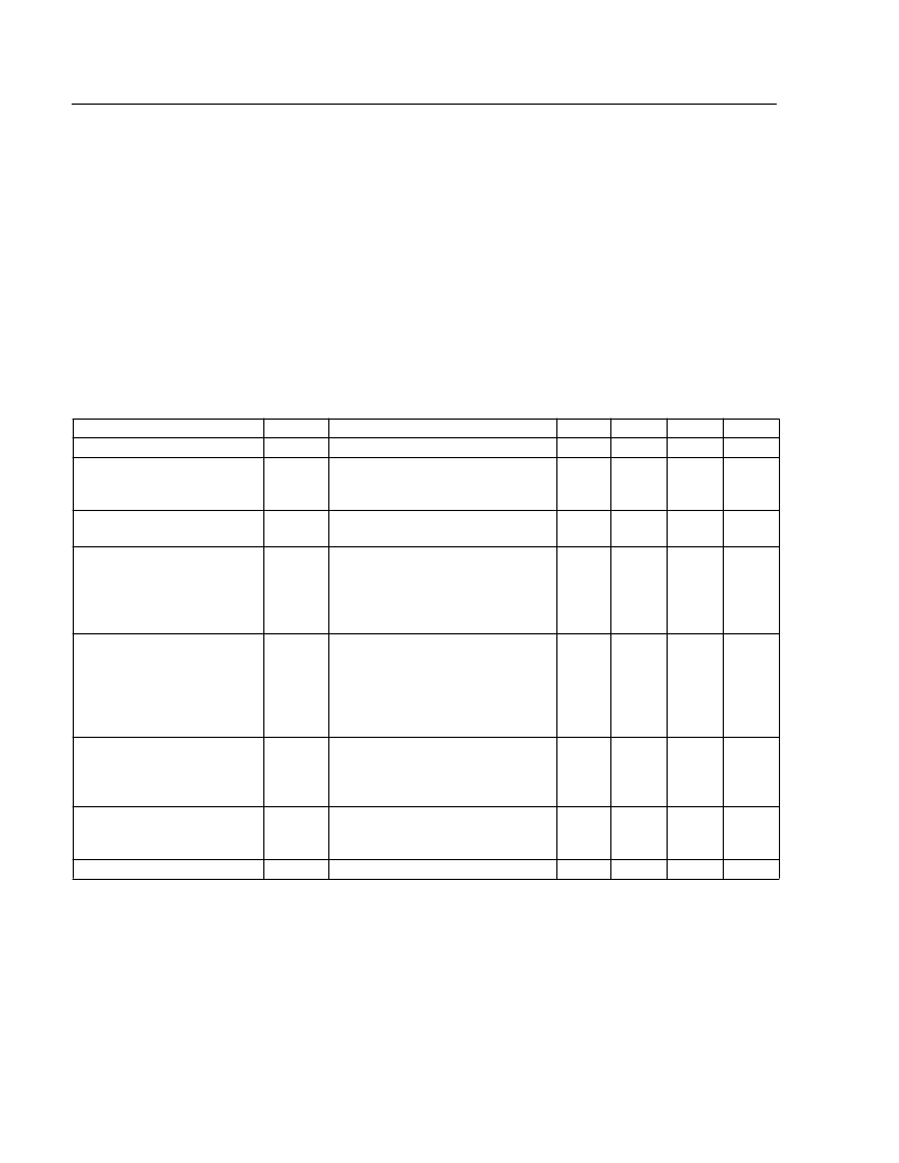
Table 3. Analog Characteristics
Parameter
Symbol
P
RIN
Test Conditions
CW, T = –40
CW, P
F
Freq. = 5 MHz to 300 MHz;
no fiber loss, T = –40
–3 dB, P
T = –40
°
T = 25
°
C, P
F
= 2.0 mW, OMI = 0.2;
Two-tone test: f1 = 13 MHz,
f2 = 19 MHz; 20 km of fiber,
(7 dB loss) plus connector loss,
f1
±
T = 25
°
C, P
F
= 2.0 mW, OMI = 0.2;
Two-tone test: f1 = 13 MHz,
f2 = 19 MHz; 20 km of fiber
(7 dB loss), plus connector loss,
all peaks from 5 MHz—50 MHz
meet this level
T = 25
°
C, P
F
= 2.0 mW, OMI = 0.2;
ref. to one-tone: 5 MHz to 50 MHz,
20 km of fiber, (7 dB loss) plus
connector loss
T = 25
°
C, P
Min
—
—
Typ
2.0
–155
Max
—
–145
Unit
mW
dB/Hz
Output Power*
Relative Intensity Noise
O
°
C to +85
= 2.0 mW,
°
C
°
C to +85
°
C
Modulation Bandwidth
BW
F
C to +85
= 2.0 mW,
°
C
1.0
—
—
GHz
Second-order Distortions
—
f2
—
–54
–58
–46
–50
–54
–42
dBc
dBc
dBc
Third-order Distortions
—
—
–70
–75
–69
–63
–68
–61
dBc
dBc
dBc
Spurious Noise
N
SP
—
–63
–61
–60
–58
§
dBc
dBc
Spurious Noise (carrier off)
N'
SP
F
= 2.0 mW
—
–50
–54
–45
—
–45
–50
–40
1.0
dBc
dBc
dBc
dB
RF Bandpass Flatness
B
P
F
Peak to valley, 5 MHz to 200 MHz
—
相關(guān)PDF資料 |
PDF描述 |
|---|---|
| A371-24AS | A371-Type Analog Uncooled Isolated DFB FastLight ⑩ Laser Module |
| A371-24BS | A371-Type Analog Uncooled Isolated DFB FastLight ⑩ Laser Module |
| A371-24FS | A371-Type Analog Uncooled Isolated DFB FastLight ⑩ Laser Module |
| A371-24GS | A371-Type Analog Uncooled Isolated DFB FastLight ⑩ Laser Module |
| A371-24NS | A371-Type Analog Uncooled Isolated DFB FastLight ⑩ Laser Module |
相關(guān)代理商/技術(shù)參數(shù) |
參數(shù)描述 |
|---|---|
| A371-24AS | 制造商:AGERE 制造商全稱:AGERE 功能描述:A371-Type Analog Uncooled Isolated DFB FastLight ⑩ Laser Module |
| A371-24BS | 制造商:AGERE 制造商全稱:AGERE 功能描述:A371-Type Analog Uncooled Isolated DFB FastLight ⑩ Laser Module |
| A371-24FS | 制造商:AGERE 制造商全稱:AGERE 功能描述:A371-Type Analog Uncooled Isolated DFB FastLight ⑩ Laser Module |
| A371-24GS | 制造商:AGERE 制造商全稱:AGERE 功能描述:A371-Type Analog Uncooled Isolated DFB FastLight ⑩ Laser Module |
| A371-24NS | 制造商:AGERE 制造商全稱:AGERE 功能描述:A371-Type Analog Uncooled Isolated DFB FastLight ⑩ Laser Module |
發(fā)布緊急采購,3分鐘左右您將得到回復(fù)。