- 您現(xiàn)在的位置:買賣IC網(wǎng) > PDF目錄362016 > A3CA-7021 SCHALTER GRUNDELEMENT QUADRATISCH PDF資料下載
參數(shù)資料
| 型號: | A3CA-7021 |
| 英文描述: | SCHALTER GRUNDELEMENT QUADRATISCH |
| 中文描述: | SCHALTER GRUNDELEMENT QUADRATISCH |
| 文件頁數(shù): | 5/6頁 |
| 文件大小: | 203K |
| 代理商: | A3CA-7021 |
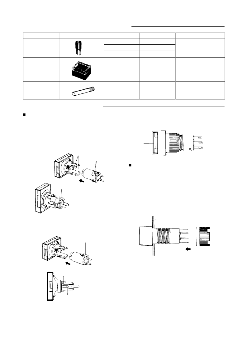
Accessories (Order Separately)
Name
Socket
Shape
Classification
Wire-wrap
terminal
Model
A3C–4101
Remarks
–
PCB terminal
A3C–4102
Solder terminal
A3C–4103
Switch guard
Rectangular
A3CJ–5050
–
T
ightening tool
–
A3C–3004
Useful for mounting switch
units one after another
. Do not
over-tighten.
Assembly/Disassembly
Mounting and Replacing Pushbutton
Unit
Mounting directions for the LED/lamp and
Screen
The
OMRON screen doubles the roles in which a pushbutton switch
is
normally used. The screen may be inserted one of two ways:
1. For
operation as a lighted pushbutton switch, fit the LED/lamp
so that its guide projection is inserted into the
wider opening in
the
receptacle of the screen.
Projection
LED/lamp
guide
LED/lamp
guide
2.
For operation as an indicator unit, insert the LED/lamp guide
projection into the narrower opening in the indicator unit’s
receptacle.
Push the projection of the LED/lamp in the groove
of
the screen so that the LED/lamp is firmly inserted into
the
screen of the indicator unit.
LED/lamp
guide
Groove of the indicator unit
Projection of the LED/lamp
Note:
The inserting direction of the LED/lamp for the screen is
opposite to that for the indicator unit. Pay attention to the
mounting
direction of the legend plate.
Removing the pushbutton unit
While
holding the recessed portions on both sides, firmly and steadily
pull
out the top of the screen with your thumb and forefinger
. Pulling
out the cap with pliers or a similar tool will damage the cap.
Recess
Mounting the switch unit on panel
Nut mounting
Insert
the switch unit from the front of the panel and tighten the
mounting
nut inserted from the rear of the panel.
Since
a projection exists on the rear portion of the switch unit, if the
mounting
unit cannot be fitted into position, turn the nut slightly
.
The
tightening
torque of the mounting nut should be less than
5kg–cm.
Solder the terminals after mounting the nut. Otherwise, the
terminals, when thickened by solder, may prevent the nut from
being
screwed down onto the switch unit.
Wiring
Finish soldering within 5 seconds with a 30 watt soldering
iron,
or within 3 seconds at a solder temperature of
240
C.
Do not apply any force to the switch unit for about a minute
after
soldering, to avoid deforming the softened plastic base
of
the switch unit.
Use a non-corrosive, resin-based soldering flux.
相關(guān)PDF資料 |
PDF描述 |
|---|---|
| A3G-4011 | SOCKEL EINPOLIG |
| A3G-4021 | SOCKEL ZWEIPOLIG |
| A3GA-510D | LINSE OR.QUADRAT. |
| A3GA-510GN | LINSE GN.QUADRAT. |
| A3GA-6011-3 | GEHAEUSE 18X18MM |
相關(guān)代理商/技術(shù)參數(shù) |
參數(shù)描述 |
|---|---|
| A3CA7111 | 制造商:OMRON AUTOMATION AND SAFETY 功能描述:SWITCH UNIT-IP40 制造商:OMRON INDUSTRIAL AUTOMATION 功能描述:SWITCH UNIT-IP40 |
| A3CA-7111 | 功能描述:開關(guān)配件 SWITCH UNIT-IP40 RoHS:否 制造商:C&K Components 類型:Cap 用于:Pushbutton Switches 設(shè)計目的: |
| A3CA7121 | 制造商:OMRON INDUSTRIAL AUTOMATION 功能描述:SWITCH UNIT-IP40 |
| A3CA-7121 | 功能描述:開關(guān)配件 SWITCH UNIT-IP40 RoHS:否 制造商:C&K Components 類型:Cap 用于:Pushbutton Switches 設(shè)計目的: |
| A3CA7121NC | 制造商:OMRON AUTOMATION AND SAFETY 功能描述:SWITCH UNIT-IP40 |
發(fā)布緊急采購,3分鐘左右您將得到回復(fù)。