- 您現(xiàn)在的位置:買賣IC網(wǎng) > PDF目錄362031 > A54SX08A1FG144M Logic IC PDF資料下載
參數(shù)資料
| 型號(hào): | A54SX08A1FG144M |
| 英文描述: | Logic IC |
| 中文描述: | 邏輯IC |
| 文件頁(yè)數(shù): | 13/36頁(yè) |
| 文件大?。?/td> | 833K |
| 代理商: | A54SX08A1FG144M |
第1頁(yè)第2頁(yè)第3頁(yè)第4頁(yè)第5頁(yè)第6頁(yè)第7頁(yè)第8頁(yè)第9頁(yè)第10頁(yè)第11頁(yè)第12頁(yè)當(dāng)前第13頁(yè)第14頁(yè)第15頁(yè)第16頁(yè)第17頁(yè)第18頁(yè)第19頁(yè)第20頁(yè)第21頁(yè)第22頁(yè)第23頁(yè)第24頁(yè)第25頁(yè)第26頁(yè)第27頁(yè)第28頁(yè)第29頁(yè)第30頁(yè)第31頁(yè)第32頁(yè)第33頁(yè)第34頁(yè)第35頁(yè)第36頁(yè)
v2.0
13
54SX Family FPGAs RadTolerant and HiRel
Power Dissipation
P = [I
CC
standby + I
CC
active] * V
CCA
+ I
OL
* V
OL
* N +
I
OH
*(V
CCA
–
V
OH
) * M
where:
I
CC
standby is the current flowing when no inputs or
outputs are changing.
I
CC
active is the current flowing due to CMOS switching.
I
OL
, I
OH
are TTL sink/source currents.
V
OL
, V
OH
are TTL level output voltages.
N equals the number of outputs driving TTL loads to V
OL
.
M equals the number of outputs driving TTL loads to V
OH
.
Accurate values for N and M are difficult to determine
because they depend on the design and on the system I/O.
The power can be divided into two components: static and
active.
Static Power Component
The power due to standby current is typically a small
component of the overall power. Standby power is shown
below for military, worst case conditions (70
°
C).
I
CC
V
CC
20 mA
3.6V
Active Power Component
Power dissipation in CMOS devices is usually dominated by
the active (dynamic) power dissipation. This component is
frequency-dependent, a function of the logic and the
external I/O. Active power dissipation results from charging
internal
chip
capacitances
unprogrammed antifuses, module inputs, and module
outputs, plus external capacitance due to PC board traces
of
the
interconnect,
and load device inputs. An additional component of the
active power dissipation is the totempole current in CMOS
transistor pairs. The net effect can be associated with an
equivalent capacitance that can be combined with
frequency and voltage to represent active power dissipation.
Equivalent Capacitance
The power dissipated by a CMOS circuit can be expressed by
Equation 1:
Power (μW) = C
EQ
* V
CCA2
* F
where:
C
EQ
= Equivalent capacitance in pF
V
CCA
= Power supply in volts (V)
F
= Switching frequency in MHz
(1)
Equivalent capacitance is calculated by measuring
I
CC
active at a specified frequency and voltage for each
circuit component of interest. Measurements have been
made over a range of frequencies at a fixed value of V
CCA
.
Equivalent capacitance is frequency-independent so that
the results may be used over a wide range of operating
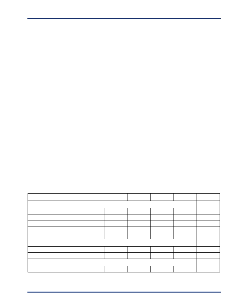
conditions. Equivalent capacitance values are shown below.
C
EQ
Values (pF)
To calculate the active power dissipated from the complete
design, the switching frequency of each part of the logic
must be known. Equation 2 shows a piece-wise linear
summation over all components.
Power =V
CCA2
* [(m * C
EQM
* f
m
)
modules
+
(n * C
EQI
* f
n
)
inputs
+ (p * (C
EQO
+ C
L
) * f
p
)
outputs
+
0.5 * (q
1
* C
EQCR
* f
q1
)
routed_Clk1
+ (r
1
* f
q1
)
routed_Clk1
+
0.5 * (q
2
* C
EQCR
* f
q2
)
routed_Clk2
+ (r
2
* f
q2
)
routed_Clk2
+
0.5 * (s
1
* C
EQCD
* f
s1
)
dedicated_CLK
]
(2)
Power
72 mW
RT54SX16
A54SX16
RT54SX32
A54SX32
Equivalent Capacitance (pF)
Modules
C
EQM
C
EQI
C
EQO
C
EQCR
C
EQCD
7.0
3.9
7.0
3.9
Input Buffers
2.0
1.0
2.0
1.0
Output Buffers
10.0
5.0
10.0
5.0
Routed Array Clock Buffer Loads
0.4
0.2
0.6
0.3
Dedicated Clock Buffer Loads
0.25
0.15
0.34
0.23
Fixed Capacitance (pF)
routed_Clk1
r
1
r
2
120
60
210
107
routed_Clk2
120
60
210
107
Fixed Clock Loads
Clock Loads on Dedicated Array Clock
s
1
528
528
1,080
1,080
相關(guān)PDF資料 |
PDF描述 |
|---|---|
| A54SX08AFG144 | Logic IC |
| A54SX08AFG144I | Logic IC |
| A54SX08AFG144M | Logic IC |
| A54SX08-FG144 | Field Programmable Gate Array (FPGA) |
| A54SX08-FG144I | Field Programmable Gate Array (FPGA) |
相關(guān)代理商/技術(shù)參數(shù) |
參數(shù)描述 |
|---|---|
| A54SX08A-1FG208 | 制造商:未知廠家 制造商全稱:未知廠家 功能描述:SX-A Family FPGAs |
| A54SX08A-1FG208A | 制造商:未知廠家 制造商全稱:未知廠家 功能描述:SX-A Family FPGAs |
| A54SX08A-1FG208B | 制造商:未知廠家 制造商全稱:未知廠家 功能描述:SX-A Family FPGAs |
| A54SX08A-1FG208I | 制造商:未知廠家 制造商全稱:未知廠家 功能描述:SX-A Family FPGAs |
| A54SX08A-1FG208M | 制造商:未知廠家 制造商全稱:未知廠家 功能描述:SX-A Family FPGAs |
發(fā)布緊急采購(gòu),3分鐘左右您將得到回復(fù)。