- 您現(xiàn)在的位置:買賣IC網(wǎng) > PDF目錄362073 > ACT-F512K8-120P4M x8 Flash EEPROM PDF資料下載
參數(shù)資料
| 型號: | ACT-F512K8-120P4M |
| 英文描述: | x8 Flash EEPROM |
| 中文描述: | x8閃存EEPROM的 |
| 文件頁數(shù): | 8/21頁 |
| 文件大小: | 153K |
| 代理商: | ACT-F512K8-120P4M |
Aeroflex Circuit Technology
SCD1676 REV A 5/6/98 Plainview NY (516) 694-6700
8
D
5
EXCEEDED TIMING LIMITS
D
5
will indicate if the program or erase time has
exceeded the specified limits. Under these conditions
D
5
will produce a "1". The Program or erase cycle was
not successfully completed. Data Polling is the only
operation function of the device under this condition.
The CE circuit will partially power down the device under
these conditions by approximately 8 mA per chip. The
OE and WE pins will control the output disable functions
as shown in Table 1. To reset the device, write the reset
command sequence to the device. This allows the
system to continue to use the other active sectors in the
device.
D4 - HARDWARE SEQUENCE FLAG
If the device has exceeded the specified erase or
program time and D5 is "1", then D4 Will indicate which
step in the algorithm the device exceeded the limits. A
"0" in D4 indicates in programming, a "1" indicates an
erase. (See Table 4)
D
3
SECTOR ERASE TIMER
After the completion of the initial sector erase command
sequence the sector erase time-out will begin. D
3
will
remain low until the time-out is complete. Data Polling
and Toggle Bit are valid after the initial sector erase
command sequence.
If Data Polling or the Toggle Bit indicates the device has
been written with a valid erase command, D
3
may be
used to determine if the sector erase timer window is still
open. If D
3
is high ("1") the internally controlled erase
cycle has begun; attempts to write subsequent
commands to the device will be ignored until the erase
operation is completed as indicated by Data Polling or
Toggle Bit. If D
3
is low ("0"), the device will accept
additional sector erase commands. To ensure the
command has been accepted, the software should check
the status of D
3
prior to and following each subsequent
sector erase command. If D
3
were high on the second
status check, the command may not have been
accepted.
Sector Protection
Algorithims
SECTOR PROTECTION
The ACT-F128K8 features hardware sector protection
which will disable both program and erase operations to
an individual sector or any group of sectors. To activate
this mode, the programming equipment must force V
ID
on control pin OE and address pin A
9
. The sector
addresses should be set using higher address lines A
16
,
A
15
, and A
14
. The protection mechanism begins on the
falling edge of the WE pulse and is terminated with the
rising edge of the same.
It is also possible to verify if a sector is protected during
the sector protection operation. This is done by setting
CE = OE = V
IL
and WE = V
IH
(A
9
remains high at V
ID
).
Reading the device at address location XXX2H, where
the higher order addresses (A16, A15 and A14) define a
particular sector, will produce 01H at data outputs D0 -
D7, for a protected sector.
SECTOR UNPROTECT
The ACT-F128K8 also features a sector unprotect mode,
so that a protected sector may be unprotected to
incorporate any changes in the code. All sectors should
be protected prior to unprotecting any sector.
To activate this mode, the programming equipment must
force V
ID
on control pins OE, CE, and address pin A9.
The address pins A
6
, A
7
, and A
12
should be set to V
IH
,
and A
6 =
V
IL
. The unprotection mechanism begins on
the falling edge of the WE pulse and is terminated with
the rising edge of the same.
It is also possible to determine if a sector is unprotected
in the system by writing the autoselect command.
Performing a read operation at address location XXX2H,
where the higher order addresses (A
16
, A
15
, and A
14
)
define a particular sector address, will produce 00H at
data outputs (D
0
-D
7
) for an unprotected sector.
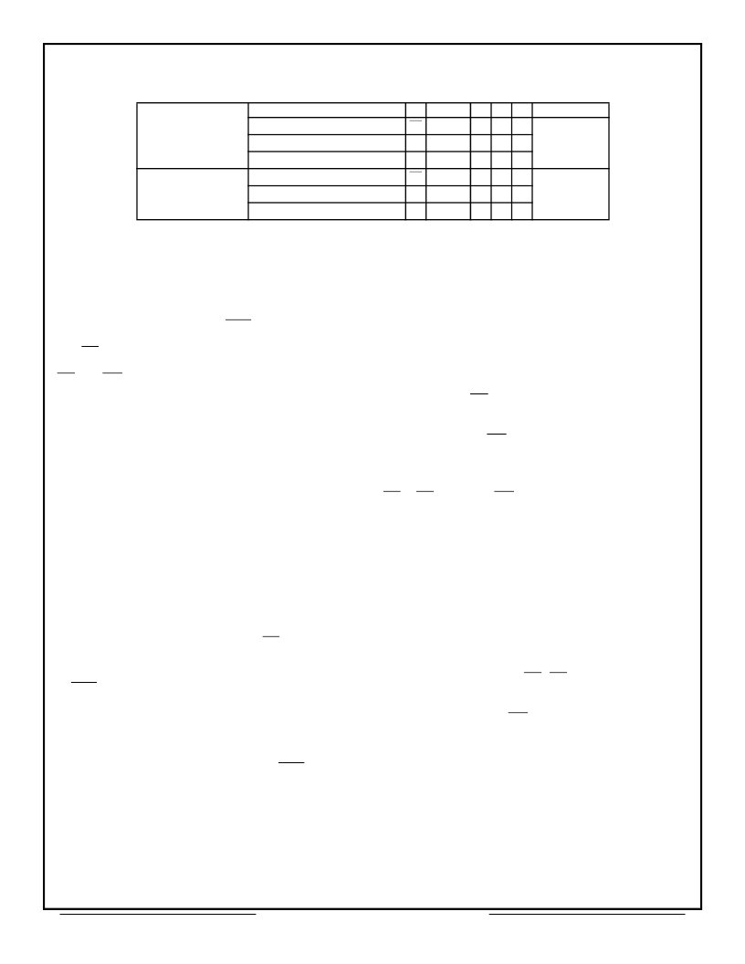
Table 4 — Hardware Sequence Flags
In Progress
Status
D
7
D7
D
6
D
5
0
D
4
0
D
3
0
D
2
– D
0
Auto-Programming
Toggle
Reserved for
future use
Programming in Auto Erase
0
Toggle
0
0
1
Erase in Auto Erase
0
Toggle
0
1
1
Exceeding Time Limits
Auto-Programming
D7
Toggle
1
0
0
Reserved for
future use
Programming in Auto Erase
T0
Toggle
1
0
1
Erase in Auto Erase
0
Toggle
1
1
1
相關(guān)PDF資料 |
PDF描述 |
|---|---|
| ACT-F512K8-150F3M | x8 Flash EEPROM |
| ACT-S512K32N-035F1Q | x32 SRAM Module |
| ACT-S512K32N-035F2Q | x32 SRAM Module |
| ACT-S512K32N-035P1Q | x32 SRAM Module |
| ACT-S512K32N-045F1Q | x32 SRAM Module |
相關(guān)代理商/技術(shù)參數(shù) |
參數(shù)描述 |
|---|---|
| ACT-F512K8-150F3M | 制造商:未知廠家 制造商全稱:未知廠家 功能描述:x8 Flash EEPROM |
| ACT-F512K8N-060F6C | 制造商:AEROFLEX 制造商全稱:AEROFLEX 功能描述:ACT-F512K8 High Speed 4 Megabit Monolithic FLASH |
| ACT-F512K8N-060F6I | 制造商:AEROFLEX 制造商全稱:AEROFLEX 功能描述:ACT-F512K8 High Speed 4 Megabit Monolithic FLASH |
| ACT-F512K8N-060F6M | 制造商:AEROFLEX 制造商全稱:AEROFLEX 功能描述:ACT-F512K8 High Speed 4 Megabit Monolithic FLASH |
| ACT-F512K8N-060F6Q | 制造商:AEROFLEX 制造商全稱:AEROFLEX 功能描述:ACT-F512K8 High Speed 4 Megabit Monolithic FLASH |
發(fā)布緊急采購,3分鐘左右您將得到回復。