- 您現(xiàn)在的位置:買(mǎi)賣(mài)IC網(wǎng) > PDF目錄373859 > AD1837AASZ-REEL (ANALOG DEVICES INC) 2 ADC, 8 DAC, 96 kHz, 24-Bit Codec PDF資料下載
參數(shù)資料
| 型號(hào): | AD1837AASZ-REEL |
| 廠商: | ANALOG DEVICES INC |
| 元件分類(lèi): | 消費(fèi)家電 |
| 英文描述: | 2 ADC, 8 DAC, 96 kHz, 24-Bit Codec |
| 中文描述: | SPECIALTY CONSUMER CIRCUIT, PQFP52 |
| 封裝: | LEAD FREE, PLASTIC, MS-022AC, MQFP-52 |
| 文件頁(yè)數(shù): | 13/24頁(yè) |
| 文件大小: | 401K |
| 代理商: | AD1837AASZ-REEL |
第1頁(yè)第2頁(yè)第3頁(yè)第4頁(yè)第5頁(yè)第6頁(yè)第7頁(yè)第8頁(yè)第9頁(yè)第10頁(yè)第11頁(yè)第12頁(yè)當(dāng)前第13頁(yè)第14頁(yè)第15頁(yè)第16頁(yè)第17頁(yè)第18頁(yè)第19頁(yè)第20頁(yè)第21頁(yè)第22頁(yè)第23頁(yè)第24頁(yè)
REV. A
AD1837A
–13–
Control Register 2, the serial mode can be changed to right-
justified (RJ), left-justified DSP (DSP), or left-justified (LJ).
In the RJ mode, it is necessary to set Bits 4 and 5 to define the
width of the data-word.
The DAC serial data input mode defaults to I
2
S. By changing
Bits 5, 6, and 7 in DAC Control Register 1, the mode can be
changed to RJ, DSP, LJ, Packed Mode 1, or Packed Mode 2. The
word width defaults to 24 bits but can be changed by reprogram-
ming Bits 3 and 4 in DAC Control Register 1.
Packed Modes
The AD1837A packed mode allows a DSP or other controller to
write to all DACs and read all ADCs using one input data pin
and one output data pin. Packed Mode 256 refers to the number
of BCLKs in each frame. The LRCLK is low while data from a
left channel DAC or ADC is on the data pin and high while data
from a right channel DAC or ADC is on the data pin. DAC data is
applied on the DSDATA1 pin, and ADC data is available on the
ASDATA pin. Figures 7 to 10 show the timing
for the packed
mode. Packed mode is available for 48 kHz and 96 kHz.
Auxiliary (TDM) Mode
A special auxiliary mode is provided to allow three external stereo
ADCs to be interfaced to the AD1837A to provide 8-in/8-out
operation. In addition, this mode supports glueless interface to a
single SHARC
DSP serial port, allowing a SHARC DSP to
access all eight channels of analog I/O. In this special mode,
many pins are redefined; see Table IV for a list of redefined pins.
The auxiliary and the TDM interfaces are independently
configurable to operate as masters or slaves. When the auxiliary
interface is set as a master, by programming the Auxiliary Mode
bit in ADC Control Register 2, AUXLRCLK and AUXBCLK are
generated by the AD1837A. When the auxiliary interface is set
as a slave, AUXLRCLK and AUXBCLK need to be generated
by an external ADC, as shown in Figure 13.
The TDM interface can be set to operate as a master or slave by
connecting the
M
/S pin to DGND or ODVDD, respectively. In
master mode, the FSTDM and BCLK signals are outputs gener-
ated by the AD1837A. In slave mode, FSTDM and BCLK are
inputs and should be generated by the SHARC. Both 48 kHz
and 96 kHz operations are available (based on a 12.288 MHz or
24.576 MHz MCLK) in this mode.
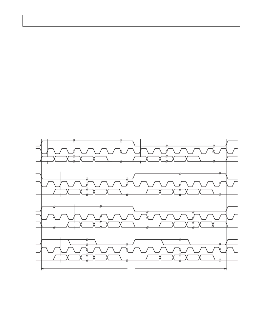
LRCLK
BCLK
SDATA
LRCLK
BCLK
SDATA
LRCLK
BCLK
SDATA
LRCLK
BCLK
SDATA
LEFT CHANNEL
RIGHT CHANNEL
LEFT CHANNEL
RIGHT CHANNEL
LEFT CHANNEL
RIGHT CHANNEL
MSB
MSB
MSB
MSB
MSB
MSB
MSB
MSB
LSB
LSB
LSB
LSB
LSB
LSB
LSB
LSB
LEFT-JUSTIFIED MODE—16 BITS TO 24 BITS PER CHANNEL
I
2
S MODE—16 BITS TO 24 BITS PER CHANNEL
RIGHT-JUSTIFIED MODE—SELECT NUMBER OF BITS PER CHANNEL
DSP MODE—16 BITS TO 24 BITS PER CHANNEL
1/
f
S
NOTES
1. DSP MODE DOES NOT IDENTIFY CHANNEL.
2. LRCLK NORMALLY OPERATES AT
f
S
EXCEPT FOR DSP MODE, WHICH IS 2
f
S.
3. BCLK FREQUENCY IS NORMALLY 64 LRCLK BUT MAY BE OPERATED IN BURST MODE.
Figure 4. Stereo Serial Modes
相關(guān)PDF資料 |
PDF描述 |
|---|---|
| AD1837 | 2 ADC, 8 DAC, 96 kHz, 24-Bit Codec |
| AD1837AS | 2 ADC, 8 DAC, 96 kHz, 24-Bit Codec |
| AD1837AS-REEL | 2 ADC, 8 DAC, 96 kHz, 24-Bit Codec |
| AD1838AASZ-REEL | 2 ADC, 6 DAC, 96KHZ 24 BIT CODEC |
| AD1838AASZ | CHOKE COIL 22UH 1300MA SMD |
相關(guān)代理商/技術(shù)參數(shù) |
參數(shù)描述 |
|---|---|
| AD1837AS | 制造商:Analog Devices 功能描述:Audio Codec 2ADC / 8DAC 24-Bit 52-Pin MQFP 制造商:Rochester Electronics LLC 功能描述:- Bulk |
| AD1837AS-REEL | 制造商:Analog Devices 功能描述:Audio Codec 2ADC / 8DAC 24-Bit 52-Pin MQFP T/R |
| AD1838 | 制造商:AD 制造商全稱(chēng):Analog Devices 功能描述:2 ADC, 6 DAC,96 kHz, 24-Bit Codec |
| AD1838A | 制造商:AD 制造商全稱(chēng):Analog Devices 功能描述:2 ADC, 6 DAC, 96KHZ 24 BIT CODEC |
| AD1838AAS | 制造商:Analog Devices 功能描述:Audio Codec 2ADC / 6DAC 24-Bit 52-Pin MQFP 制造商:Rochester Electronics LLC 功能描述:HIGH PERFORMANCE CODEC - Bulk 制造商:Analog Devices 功能描述:IC CODEC SMD 1838 MQFP52 |
發(fā)布緊急采購(gòu),3分鐘左右您將得到回復(fù)。