- 您現(xiàn)在的位置:買賣IC網(wǎng) > PDF目錄373864 > AD20MSP410 (ANALOG DEVICES INC) Circular Connector; MIL SPEC:MIL-DTL-38999 Series I; Body Material:Metal; Series:LJT; No. of Contacts:16; Connector Shell Size:21; Connecting Termination:Crimp; Circular Shell Style:Wall Mount Receptacle; Body Style:Straight RoHS Compliant: No PDF資料下載
參數(shù)資料
| 型號: | AD20MSP410 |
| 廠商: | ANALOG DEVICES INC |
| 元件分類: | 通信及網(wǎng)絡(luò) |
| 英文描述: | Circular Connector; MIL SPEC:MIL-DTL-38999 Series I; Body Material:Metal; Series:LJT; No. of Contacts:16; Connector Shell Size:21; Connecting Termination:Crimp; Circular Shell Style:Wall Mount Receptacle; Body Style:Straight RoHS Compliant: No |
| 中文描述: | SPECIALTY TELECOM CIRCUIT |
| 文件頁數(shù): | 3/8頁 |
| 文件大小: | 62K |
| 代理商: | AD20MSP410 |
AD20msp410
–3–
REV. 0
decision confidence bits supplied by the equalizer. Once these
decoding functions are complete, digitized voice data is trans-
ferred to the ASP through a parallel port. Error control mecha-
nisms are used to ensure adequate bad frame indication.
Speech Decoding (ASP)
Encoded speech data is transferred at 20 ms intervals from the
PLP to the ASP in blocks of 260 bits plus the Bad Frame
Indicator (BFI). T he speech decoder supports a Comfort Noise
Insertion (CNI) function that inserts a predefined silence
descriptor into the decoding process. T he ASP also implements
control of talker side-tone and short term echo cancellation.
T he resulting data, at 104 kb/s, is transferred to the BBC
through a dedicated serial path.
Voice Digital-to-Analog Conversion
T he Voice DAC function of the BBC uses a sigma-delta con-
verter to convert and noise shape the signal. T he 13-bit linear
values are converted to the analog domain and filtered to avoid
any images. T he resulting differential signals can be controlled
in volume and drive directly a small earpiece as well as a
separate auxiliary output.
AUX ILIARY SY ST E M FUNCT IONS
T he ASP, the PLP and the BBC perform a number of auxiliary
functions which are essential to build a complete mobile radio.
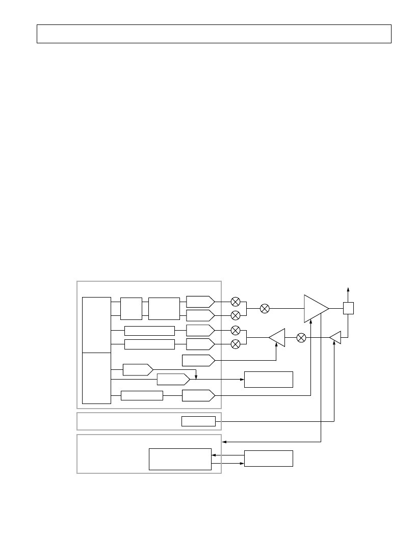
A general radio section constitutes the three functions of
transmitter, receiver and synthesizer. Figure 2 shows how the
baseband chipset interfaces to a typical radio architecture. T he
transmitter is fed with baseband analog I and Q signals from the
BBC and upconverted to 900 MHz for GSM applications and
1800 MHz for PCN applications.
A dedicated power amplifier increases the RF-signal to the
required level. T he receiver amplifies the antenna signal, down-
converts it to an intermediate frequency (IF) and amplifies it
there again. After second conversion to baseband, the I and Q
components of the signal are fed into the BBC.
T he BBC, ASP and PLP provide three auxiliary functions for
interfacing to the radio subsystem. T hese auxiliary functions
include AGC, AFC and Power Ramping.
Power Ramp E nvelope (BBC)
T o meet the spectral and time-domain specifications of the
transmitted output signal, the burst has to follow a specified
power envelope. T he envelope for the power profile originates in
the PLP as a set of coefficients, down-loaded and stored in the
BBC. T his envelope profile is sent to one of the auxiliary DACs
on the BBC with each burst. T he analog output is fed into the
RF power amplifier, controlling the power profile and absolute
level of the transmitted data.
Automatic Gain Control (AGC)
T he mobile radio has to cope with a wide range of input signal
levels. T he major part of the overall gain is provided in the IF
amplifier. T he incoming signal level is analyzed in the ASP and
the PLP and a digital gain control signal is sent to the BBC. A
10-bit auxiliary DAC generates the appropriate analog control
signal for the IF amplifier. Additionally gain control can be
implemented by using two output flags of the ASP.
FLAGS
13 MHz VCTCXO
13 MHz VCTCXO
SYNTHESIZER
CONTROL SIGNALS
AGC
AFC
RAMP CONTROL
AGC
PAERROR
LOCK
10-BIT DAC
I
Q
I
Q
PLP
ASP
BASEBAND/AUXILIARY SECTION OF AD7015
DDIGITAL FIR FILTER
RAMPING RAM
GSMSK
MODULATOR
BURST
STORE
PA
IF
T
X
DAC
T
X
DAC
10-BIT DAC
10-BIT DAC
8-BIT DAC
DIGITAL FIR FILTER
R
X
DAC
R
X
DAC
BASEBAND
SERIAL
INTERFACE
AUXILIARY
SERIAL
INTERFACE
Figure 2. Control of RF Section
相關(guān)PDF資料 |
PDF描述 |
|---|---|
| ADSP-2178-780244 | GSM Baseband Processing Chipset |
| ADPLP01 | GSM Baseband Processing Chipset |
| AD20MSP415 | Circular Connector; No. of Contacts:79; Series:LJTPQ00R; Body Material:Aluminum; Connecting Termination:Crimp; Connector Shell Size:21; Circular Contact Gender:Pin; Circular Shell Style:Wall Mount Receptacle |
| AD6422AST | surface mount silicon Zener diodes |
| AD6423 | DIODE ZENER 5.6V 500MW |
相關(guān)代理商/技術(shù)參數(shù) |
參數(shù)描述 |
|---|---|
| AD20MSP415 | 制造商:AD 制造商全稱:Analog Devices 功能描述:GSM/DCS1800/PCS1900 Baseband Processing Chipset |
| AD20MSP700KP | 制造商:Analog Devices 功能描述: |
| AD20SI120 | 制造商:未知廠家 制造商全稱:未知廠家 功能描述:ASIC |
| AD20SI130 | 制造商:未知廠家 制造商全稱:未知廠家 功能描述:ASIC |
| AD20SI220 | 制造商:未知廠家 制造商全稱:未知廠家 功能描述:ASIC |
發(fā)布緊急采購,3分鐘左右您將得到回復(fù)。