- 您現(xiàn)在的位置:買賣IC網(wǎng) > PDF目錄373864 > AD22001* (Analog Devices, Inc.) 5-Channel Monolithic Comparator for Lamp Monitoring PDF資料下載
參數(shù)資料
| 型號(hào): | AD22001* |
| 廠商: | Analog Devices, Inc. |
| 英文描述: | 5-Channel Monolithic Comparator for Lamp Monitoring |
| 中文描述: | 5通道單片比較監(jiān)測(cè)燈 |
| 文件頁(yè)數(shù): | 6/8頁(yè) |
| 文件大小: | 146K |
AD22001
REV. A
–6–
resistance track. Bends in the track make the effective L/W more
difficult to calculate, however, certain common cases have been
evaluated.
T o calculate the resistance of a track of width W with a 180
°
bend at radius W/2 resulting in a spacing W, add a resistance
equivalent to 2.96 squares to account for the bend. Solving the
resistance equation for L/W,
L/W = R/
ρ
S
= 10.769 m
/0.25 m
/sq,
or L/W = 43 squares.
Subtracting out the bend, the remainder is 40.04 squares.
Converting this to linear dimensions gives 4.004" at W = 0.1".
AD22001
(Not to Scale)
4
5
0.05"
0.1"
0.1"
2.002"
2.002"
TO LAMP
0.1"
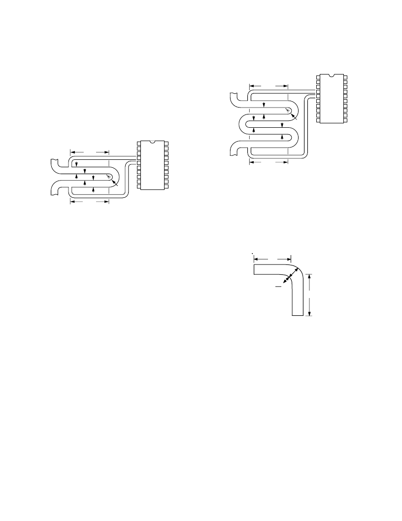
Figure 5. PCB Track Shunt Resistor with One 180
°
Bend
As shown in Figure 5, the contacts are made to the resistor
section of the track at 2.002" from the bend. T he bend has a
uniform width of W, which is 0.1" in this case, and a radius of
W/2. As a result, the aspect ratio of the straight sections plus the
bend total 2.96 squares + (2.002" + 2.002")/0.1" or 43 squares.
T he straight sections need not be of equal length, so long as
T hey have the proper total, and the shorter one is longer than
about 3W. A shorter resistor can be made by using more bends
and reducing the linear portion. For example, with three bends
the total length of four linear sections would be:
(43 squares – 3
3
2.96 squares/Bend)W
or (43 – 8.88)
3
0.1"= 3.412".
Assuming equal linear sections, the contacts and the bends
should be made at spacings of 3.412"/4 = 0.853", as shown in
Figure 6.
AD22001
(Not to Scale)
4
5
0.05"
0.1"
0.1"
0.1"
0.853"
TO LAMP
0.853"
FROM SWITCH
Figure 6. PCB Track Shunt Resistor with Two 180
°
Bends
A 90
°
bend with an inside radius of W/2 and a smooth width of
W adds 0.341 squares to the aspect ratio as shown in Figure 7.
Note that the linear measurements are differently made at the
90
°
and the 180
°
bend.
Other styles of bend can be used with minor variation in total
resistance, however, we do not recommend the use of sharp
inside corners on high current conductors in general and shunt
resistors in particular. Sharp inside corners result in very high
local current density and poor resistance repeatability.
W
W
2
W
L2
L1
Figure 7. PCB Track Shunt Resistor with 90
°
Bend
相關(guān)PDF資料 |
PDF描述 |
|---|---|
| AD22050 | Single-Supply Sensor Interface Amplifier |
| AD22050R-REEL | Single-Supply Sensor Interface Amplifier |
| AD22050N | Single-Supply Sensor Interface Amplifier |
| AD22050R | Single-Supply Sensor Interface Amplifier |
| AD22055 | ECONOLINE: RD & RC - Dual Output from a Single Input Rail- 1kVDC & 2kVDC Isolation- Power Sharing on Output- Custom Solutions Available- UL94V-0 Package Material- Efficiency to 86% |
相關(guān)代理商/技術(shù)參數(shù) |
參數(shù)描述 |
|---|---|
| AD22001-2 | 制造商:Analog Devices 功能描述: |
| AD22001N | 制造商:Analog Devices 功能描述: |
| AD22001P | 制造商:Analog Devices 功能描述: |
| AD22002 | 制造商:未知廠家 制造商全稱:未知廠家 功能描述:Analog IC |
發(fā)布緊急采購(gòu),3分鐘左右您將得到回復(fù)。