- 您現(xiàn)在的位置:買賣IC網 > PDF目錄378284 > ADC12L038CIWM (NATIONAL SEMICONDUCTOR CORP) 3.3V Self-Calibrating 12-Bit Plus Sign Serial I/O A/D Converters with MUX and Sample/Hold PDF資料下載
參數(shù)資料
| 型號: | ADC12L038CIWM |
| 廠商: | NATIONAL SEMICONDUCTOR CORP |
| 元件分類: | ADC |
| 英文描述: | 3.3V Self-Calibrating 12-Bit Plus Sign Serial I/O A/D Converters with MUX and Sample/Hold |
| 中文描述: | 8-CH 12-BIT SUCCESSIVE APPROXIMATION ADC, SERIAL ACCESS, PDSO28 |
| 封裝: | SOP-28 |
| 文件頁數(shù): | 24/36頁 |
| 文件大小: | 828K |
| 代理商: | ADC12L038CIWM |
第1頁第2頁第3頁第4頁第5頁第6頁第7頁第8頁第9頁第10頁第11頁第12頁第13頁第14頁第15頁第16頁第17頁第18頁第19頁第20頁第21頁第22頁第23頁當前第24頁第25頁第26頁第27頁第28頁第29頁第30頁第31頁第32頁第33頁第34頁第35頁第36頁
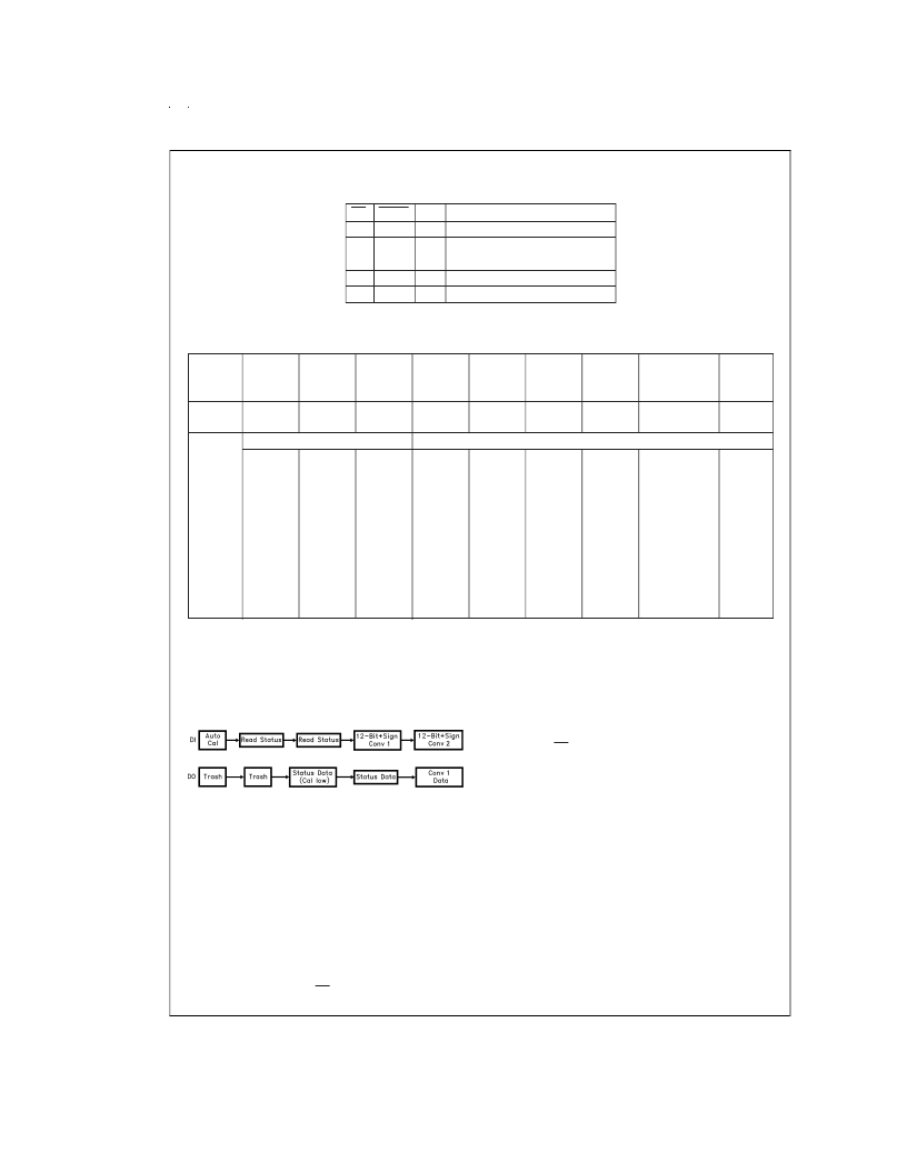
Tables
(Continued)
TABLE 6. Conversion/Read Data Only Mode Programming
CS
L
L
CONV
L
H
PD
L
L
Mode
See Table 5 for Mode
Read Only (Previous DO Format)
No Conversion
Idle
Power Down
H
X
X
X
L
H
X = Don’t Care
TABLE 7. Status Register
Status
Bit
Location
Status
Bit
DB0
DB1
DB2
DB3
DB4
DB5
DB6
DB7
DB8
PU
PD
Cal
8 or 9
12 or 13
16 or 17
Sign
Justification
Test
Mode
Device Status
DO Output Format Status
Function
“High”
indicates
a Power
Up
Sequence
is in
progress
“High”
indicates
a Power
Down
Sequence
is in
progress
“High”
indicates
an
Auto-Cal
Sequence
is in
progress
“High”
indicates
an 8 or 9
bit format
“High”
indicates
a 12 or
13 bit
format
“High”
indicates
a 16 or
17 bit
format
“High”
indicates
that the
sign bit is
included.
When
“Low” the
sign bit is
not
included.
When “High”
the conversion
result will be
output MSB
first. When
“Low” the
result will be
output LSB
first.
When
“High”
the
device is
in test
mode.
When
“Low” the
device is
in user
mode.
Application Hints
1.0 DIGITAL INTERFACE
1.1 Interface Concepts
The example in Figure 7shows a typical sequence of events
after the power is applied to the ADC12L030/2/4/8:
The first instruction input to the A/D via DI initiates Auto Cal.
The data output on DO at that time is meaningless and is
completely random. To determine whether the Auto Cal has
been completed, a read status instruction is issued to the
A/D. Again the data output at that time has no significance
since the Auto Cal procedure modifies the data in the output
shift register. To retrieve the status information, an additional
read status instruction is issued to the A/D. At this time the
status data is available on DO. If the Cal signal in the status
word is low Auto Cal has been completed. Therefore, the
next instruction issued can start a conversion. The data out-
put at this time is again status information. To keep noise
from corrupting the A/D conversion, the status can not be
read during a conversion. If CS is strobed and is brought low
during a conversion, that conversion is prematurely ended.
EOC can be used to determine the end of a conversion or
theA/D controller can keep track in software of when it would
be appropriate to communicate to the A/D again. Once it has
been determined that the A/D has completed a conversion
another instruction can be transmitted to the A/D. The data
from this conversion can be accessed when the next instruc-
tion is issued to the A/D.
Note, when CS is low continuously it is important to transmit
the exact number of SCLK cycles, as shown in the timing
diagrams. Not doing so will desynchronize the serial commu-
nication to the A/D (see Section 1.3).
1.2 Changing Configuration
The configuration of the ADC12L030/2/4/8 on power up de-
faults to 12-bit plus sign resolution, 12- or 13-bit MSB First,
10 CCLK acquisition time, user mode, no Auto Cal, no Auto
Zero, and power up mode. Changing the acquisition time
and turning the sign bit on and off requires an 8-bit instruc-
tion to be issued to the ADC. This instruction will not start a
conversion. The instructions that select a multiplexer ad-
dress and format the output data do start a conversion. Fig-
ure 8 describes an example of changing the configuration of
the ADC12L030/2/4/8.
During I/O sequence 1 the instruction on DI configures the
ADC12L030/2/4/8 to do a conversion with 12-bit +sign reso-
lution. Notice that when the 6 CCLK Acquisition and Data
Out without Sign instructions are issued to the ADC, I/O se-
quences 2 and 3, a new conversion is not started. The data
DS011830-36
FIGURE 7. Typical Power Supply Power Up Sequence
www.national.com
24
相關PDF資料 |
PDF描述 |
|---|---|
| ADC14061CCVT | Self-Calibrating 14-Bit, 2.5 MSPS, 390 mW A/D Converter |
| ADC14061 | Low Dropout Linear 2-cell Li-Ion Charge Controller with AutoCompTM, 8.4V 8-SOIC -20 to 70 |
| ADC14071CIVBH | 14-Bit, 7 MSPS, 380 mW A/D Converter |
| ADC14071 | 14-Bit, 7 MSPS, 380 mW A/D Converter |
| ADC14071EVAL | 14-Bit, 7 MSPS, 380 mW A/D Converter |
相關代理商/技術參數(shù) |
參數(shù)描述 |
|---|---|
| ADC12L038CIWM/NOPB | 功能描述:IC ADC 12BIT W/S&H +SIGN 28SOIC RoHS:是 類別:集成電路 (IC) >> 數(shù)據(jù)采集 - 模數(shù)轉換器 系列:- 產品培訓模塊:Lead (SnPb) Finish for COTS Obsolescence Mitigation Program 標準包裝:2,500 系列:- 位數(shù):12 采樣率(每秒):3M 數(shù)據(jù)接口:- 轉換器數(shù)目:- 功率耗散(最大):- 電壓電源:- 工作溫度:- 安裝類型:表面貼裝 封裝/外殼:SOT-23-6 供應商設備封裝:SOT-23-6 包裝:帶卷 (TR) 輸入數(shù)目和類型:- |
| ADC12L038CIWMX | 制造商:未知廠家 制造商全稱:未知廠家 功能描述:Single-Ended Data Acquisition System |
| ADC12L063 | 制造商:NSC 制造商全稱:National Semiconductor 功能描述:12-Bit, 62 MSPS, 354 mW A/D Converter with Internal Sample-and-Hold |
| ADC12L063CIVY | 功能描述:模數(shù)轉換器 - ADC RoHS:否 制造商:Texas Instruments 通道數(shù)量:2 結構:Sigma-Delta 轉換速率:125 SPs to 8 KSPs 分辨率:24 bit 輸入類型:Differential 信噪比:107 dB 接口類型:SPI 工作電源電壓:1.7 V to 3.6 V, 2.7 V to 5.25 V 最大工作溫度:+ 85 C 安裝風格:SMD/SMT 封裝 / 箱體:VQFN-32 |
| ADC12L063CIVY/NOPB | 功能描述:模數(shù)轉換器 - ADC RoHS:否 制造商:Texas Instruments 通道數(shù)量:2 結構:Sigma-Delta 轉換速率:125 SPs to 8 KSPs 分辨率:24 bit 輸入類型:Differential 信噪比:107 dB 接口類型:SPI 工作電源電壓:1.7 V to 3.6 V, 2.7 V to 5.25 V 最大工作溫度:+ 85 C 安裝風格:SMD/SMT 封裝 / 箱體:VQFN-32 |
發(fā)布緊急采購,3分鐘左右您將得到回復。