- 您現(xiàn)在的位置:買賣IC網(wǎng) > PDF目錄373983 > ADF4218 (Analog Devices, Inc.) Dual RF PLL Frequency Synthesizers PDF資料下載
參數(shù)資料
| 型號: | ADF4218 |
| 廠商: | Analog Devices, Inc. |
| 元件分類: | XO, clock |
| 英文描述: | Dual RF PLL Frequency Synthesizers |
| 中文描述: | 雙射頻鎖相環(huán)頻率合成器 |
| 文件頁數(shù): | 1/20頁 |
| 文件大?。?/td> | 227K |
| 代理商: | ADF4218 |
REV. 0
Information furnished by Analog Devices is believed to be accurate and
reliable. However, no responsibility is assumed by Analog Devices for its
use, nor for any infringements of patents or other rights of third parties
which may result from its use. No license is granted by implication or
otherwise under any patent or patent rights of Analog Devices.
a
ADF4216/ADF4217/ADF4218
One Technology Way, P.O. Box 9106, Norwood, MA 02062-9106, U.S.A.
Tel: 781/329-4700
World Wide Web Site: http://www.analog.com
Fax: 781/326-8703
Analog Devices, Inc., 2000
Dual RF PLL Frequency Synthesizers
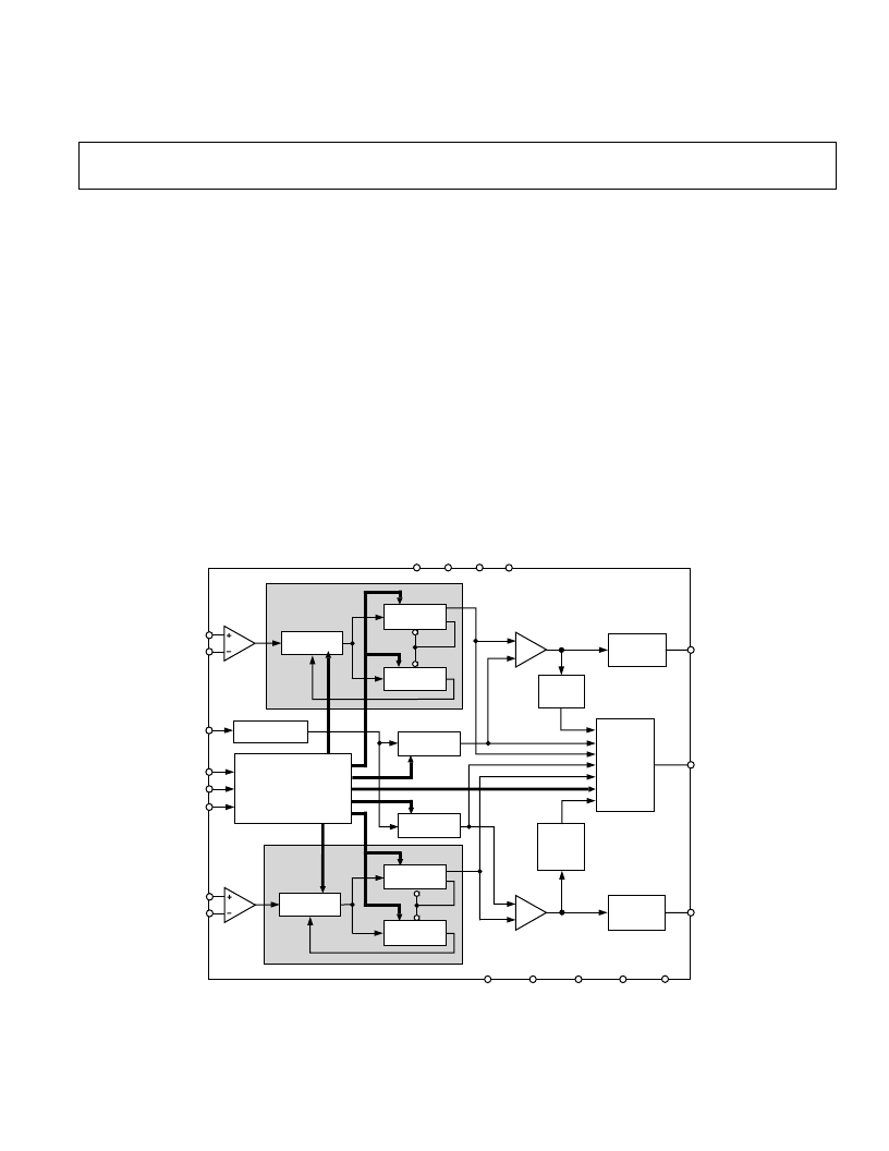
FUNCTIONAL BLOCK DIAGRAM
22-BIT
DATA
REGISTER
SDOUT
OSCILLATOR
CLOCK
DATA
LE
IF
LOCK
DETECT
MUXOUT
ADF4216/ADF4217/ADF4218
CP
RF
CP
IF
CHARGE
PUMP
PHASE
COMPARATOR
OUTPUT
MUX
REF
IN
RF
PRESCALER
RF
IN
A
CHARGE
PUMP
PHASE
COMPARATOR
RF
LOCK
DETECT
V
DD
1
V
DD
2
V
P
1
V
P
2
AGND
RF
DGND
RF
DGND
IF
AGND
IF
RF
IN
B
DGND
IF
IF
PRESCALER
IF
IN
A
IF
IN
B
11-BIT IF
B-COUNTER
6-BIT IF
A-COUNTER
N = BP + A
N = BP + A
14-BIT IF
R-COUNTER
14-BIT IF
R-COUNTER
11-BIT RF
B-COUNTER
6-BIT RF
A-COUNTER
FEATURES
ADF4216: 550 MHz/1.2 GHz
ADF4217: 550 MHz/2.0 GHz
ADF4218: 550 MHz/2.5 GHz
2.7 V to 5.5 V Power Supply
Selectable Charge Pump Currents
Selectable Dual Modulus Prescaler
IF:
8/9 or 16/17
RF: 32/33 or 64/65
3-Wire Serial Interface
Power-Down Mode
APPLICATIONS
Wireless Handsets (GSM, PCS, DCS, CDMA, WCDMA)
Base Stations for Wireless Radio (GSM, PCS, DCS,
CDMA, WCDMA)
Wireless LANS
Communications Test Equipment
CATV Equipment
GENERAL DESCRIPTION
The ADF4216/ADF4217/ADF4218 are dual frequency synthe-
sizers that can be used to implement local oscillators (LOs) in
the upconversion and downconversion sections of wireless
receivers and transmitters. They can provide the LO for both
the RF and IF sections. They consist of a low-noise digital PFD
(Phase Frequency Detector), a precision charge pump, a pro-
grammable reference divider, programmable A and B counters,
and a dual-modulus prescaler (P/P+1). The A (6-bit) and B
(11-bit) counters, in conjunction with the dual modulus prescaler
(P/P+1), implement an N divider (N = BP + A). In addition,
the 14-bit reference counter (R Counter), allows selectable
REFIN frequencies at the PFD input. A complete PLL (Phase-
Locked Loop) can be implemented if the synthesizers are
used with an external loop filter and VCOs (Voltage Con-
trolled Oscillators).
Control of all the on-chip registers is via a simple 3-wire interface.
The devices operate with a power supply ranging from 2.7 V
to 5.5 V and can be powered down when not in use.
相關(guān)PDF資料 |
PDF描述 |
|---|---|
| ADF4218BRU | Dual RF PLL Frequency Synthesizers |
| ADF4251 | Dual Fractional-N/Integer-N Frequency Synthesizer |
| ADF4251BCP | Dual Fractional-N/Integer-N Frequency Synthesizer |
| ADF4251BCP-REEL | Dual Fractional-N/Integer-N Frequency Synthesizer |
| ADF4251BCP-REEL7 | Dual Fractional-N/Integer-N Frequency Synthesizer |
相關(guān)代理商/技術(shù)參數(shù) |
參數(shù)描述 |
|---|---|
| ADF4218BRU | 制造商:Rochester Electronics LLC 功能描述: 制造商:Analog Devices 功能描述: |
| ADF4218BRU-REEL | 制造商:Analog Devices 功能描述:PLL Frequency Synthesizer Dual 20-Pin TSSOP T/R |
| ADF4218L | 制造商:未知廠家 制造商全稱:未知廠家 功能描述:ADF4217L/18L/19L: Dual Low Power Frequency Synthesizers Data Sheet (Rev. B. 7/02) |
| ADF4218LBCC | 制造商:Analog Devices 功能描述:PLL Frequency Synthesizer Dual Up to 188MHz 24-Pin LGA |
| ADF4218LBCC-REEL | 制造商:Analog Devices 功能描述:PLL Frequency Synthesizer Dual Up to 188MHz 24-Pin LGA T/R |
發(fā)布緊急采購,3分鐘左右您將得到回復(fù)。