- 您現(xiàn)在的位置:買賣IC網(wǎng) > PDF目錄10181 > ADM3307EARUZ-REEL7 (Analog Devices Inc)IC TXRX RS-232 5:3 2.7V 28TSSOP PDF資料下載
參數(shù)資料
| 型號: | ADM3307EARUZ-REEL7 |
| 廠商: | Analog Devices Inc |
| 文件頁數(shù): | 24/24頁 |
| 文件大?。?/td> | 0K |
| 描述: | IC TXRX RS-232 5:3 2.7V 28TSSOP |
| 標準包裝: | 1,000 |
| 類型: | 收發(fā)器 |
| 驅(qū)動器/接收器數(shù): | 5/3 |
| 規(guī)程: | RS232 |
| 電源電壓: | 2.7 V ~ 3.6 V |
| 安裝類型: | 表面貼裝 |
| 封裝/外殼: | 28-TSSOP(0.173",4.40mm 寬) |
| 供應(yīng)商設(shè)備封裝: | 28-TSSOP |
| 包裝: | 帶卷 (TR) |

Data Sheet
ADM3307E/ADM3310E/ADM3311E/ADM3312E/ADM3315E
Rev. I | Page 9 of 24
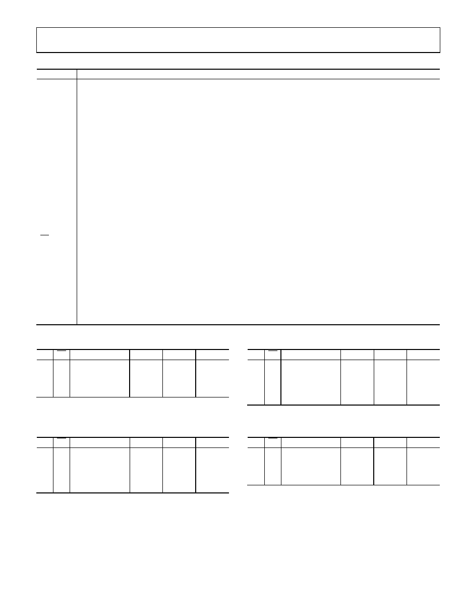
Table 4. Pin Function Descriptions
Mnemonic
Function
VCC
Power Supply Input 2.7 V to 3.6 V.
V+
Internally Generated Positive Supply, 7.25 V (6.5 V Nominal for ADM3310E, ADM3315E). Capacitor C4 is connected between
VCC and V+.
V
Internally Generated Positive Supply, 7.25 V (6.5 V Nominal for ADM3310E, ADM3315E). Capacitor C5 is connected between
GND and V.
GND
Ground Pin. Must be connected to 0 V.
C1+, C1
External Capacitor 1 is connected between these pins. A 0.1 F capacitor is recommended, but larger capacitors up to 1 F
can be used.
C2+, C2
External Capacitor 2 is connected between these pins. A 0.1 F capacitor is recommended, but larger capacitors up to 1 F
can be used.
C3+, C3
External Capacitor 3 is connected between these pins. A 0.1 F capacitor is recommended, but larger capacitors up to 1 F
can be used.
TIN
Transmitter (Driver) Inputs. These inputs accept TTL/CMOS levels. An internal 400 k pull-up resistor to VCC is connected on
each input.
TOUT
Transmitter (Driver) Outputs. Typically ±5.5 V (±6.4 V for ADM3311E and ADM3312E).
RIN
Receiver Inputs. These inputs accept RS-232 signal levels. An internal 5 k pull-down resistor (22 k for ADM3315E) to GND is
connected on each of these inputs.
ROUT
Receiver Outputs. These are TTL/CMOS levels.
EN
Receiver Enable. A high level three-states all the receiver outputs.
SD
Shutdown Control. A high level disables the charge pump and reduces the quiescent current to less than 1 A. All
transmitters and most receivers are disabled. One receiver remains active in shutdown (two receivers are active in shutdown
for the ADM3310E).
For ADM3307E, ROUT3 is active in shutdown.
For ADM3310E, ROUT4 and ROUT5 are active in shutdown.
For ADM3311E, ROUT5 is active in shutdown.
For ADM3312E, ROUT3 is active in shutdown.
For ADM3315E, ROUT3 is active in shutdown.
NC
No Connect.
Table 5. ADM3307E Truth Table
SD
EN
Status
TOUT1–5
ROUT1–2
ROUT3
0
Normal Operation
Enabled
0
1
Normal Operation
Enabled
Disabled
1
0
Shutdown
Disabled
Enabled
1
Shutdown
Disabled
Table 6. ADM3310E Truth Table
SD
EN
Status
TOUT1–3
ROUT1–3
ROUT4–5
0
Normal Operation
Enabled
0
1
Receivers
Disabled
Enabled
Disabled
1
0
Shutdown
Disabled
Enabled
1
Shutdown
Disabled
Table 7. ADM3311 Truth Table
SD
EN
Status
TOUT1–3
ROUT1–4
ROUT5
0
Normal Operation
Enabled
0
1
Receivers
Disabled
Enabled
Disabled
1
0
Shutdown
Disabled
Enabled
1
Shutdown
Disabled
Table 8. ADM3312E/ADM3315E Truth Table
SD
EN
Status
TOUT1–3
ROUT1–2
ROUT3
0
Normal Operation
Enabled
0
1
Normal Operation
Enabled
Disabled
1
0
Shutdown
Disabled
Enabled
1
Shutdown
Disabled
相關(guān)PDF資料 |
PDF描述 |
|---|---|
| CXS3106A282P | CONN PLUG 14POS STRGHT PIN |
| LTC2850CDD#TRPBF | IC TXRX RS485 20MBPS 8-DFN |
| PX0707/S/03 | CONN RCPT 3POS W/SOCKET PCB |
| MS3106E24-22S | CONN PLUG 4POS STRAIGHT W/SCKT |
| LTC1608CG | IC A/D CONV 16BIT SAMPLNG 36SSOP |
相關(guān)代理商/技術(shù)參數(shù) |
參數(shù)描述 |
|---|---|
| ADM3307EWARUZ-RL7 | 制造商:Analog Devices 功能描述: |
| ADM3310E | 制造商:AD 制造商全稱:Analog Devices 功能描述:15 kV ESD Protected, 2.7 V to 3.6 V Serial Port Transceivers with Green Idle⑩ |
| ADM3310EACP | 制造商:Analog Devices 功能描述:Triple Transmitter Quint Receiver RS-232 32-Pin LFCSP EP |
| ADM3310EACP-REEL | 制造商:Analog Devices 功能描述:Triple Transmitter Quint Receiver RS-232 32-Pin LFCSP EP T/R |
| ADM3310EACP-REEL7 | 制造商:Analog Devices 功能描述:Triple Transmitter Quint Receiver RS-232 32-Pin LFCSP EP T/R 制造商:Rochester Electronics LLC 功能描述:15KV ESD +2.7V TO 3.6V S P T I.C. - Tape and Reel |
發(fā)布緊急采購,3分鐘左右您將得到回復(fù)。