- 您現(xiàn)在的位置:買(mǎi)賣(mài)IC網(wǎng) > PDF目錄67389 > AM-1571-140 (MITEQ INC) 100 MHz - 180 MHz RF/MICROWAVE NARROW BAND LOW POWER AMPLIFIER PDF資料下載
參數(shù)資料
| 型號(hào): | AM-1571-140 |
| 廠商: | MITEQ INC |
| 元件分類(lèi): | 放大器 |
| 英文描述: | 100 MHz - 180 MHz RF/MICROWAVE NARROW BAND LOW POWER AMPLIFIER |
| 文件頁(yè)數(shù): | 21/25頁(yè) |
| 文件大?。?/td> | 1906K |
| 代理商: | AM-1571-140 |
第1頁(yè)第2頁(yè)第3頁(yè)第4頁(yè)第5頁(yè)第6頁(yè)第7頁(yè)第8頁(yè)第9頁(yè)第10頁(yè)第11頁(yè)第12頁(yè)第13頁(yè)第14頁(yè)第15頁(yè)第16頁(yè)第17頁(yè)第18頁(yè)第19頁(yè)第20頁(yè)當(dāng)前第21頁(yè)第22頁(yè)第23頁(yè)第24頁(yè)第25頁(yè)

recorded over the operating frequency range. Unless
the amplifier is specified to operate over a defined
temperature range, this measurement is per-
formed at room ambient temperature (+23°C). If a
range of temperatures is specified, the measurement
must also be verified at the temperature extremes.
NOISE FIGURE
Noise figure is classically defined as:
Since all realistic amplifiers add thermal noise, the
signal-to-noise ratio at the output will be degraded;
therefore, noise figure will be a ratio greater than one,
or when expressed in decibels, a positive number
(NFdB = 10 log10(NFRatio). The additive noise of an
amplifier can also be expressed in a parameter
referred to as noise temperature. In this approach,
the noise temperature of the amplifier is equal to the
temperature (in degrees Kelvin) of a 50
termination
at the input of an ideal noiseless amplifier with the
same gain and generating the same output noise power.
The relationship between noise figure and noise tem-
perature is :
Noise figure data is measured at discrete frequencies
throughout the band at +23°C unless specified otherwise.
OUTPUT POWER AT 1 dB COMPRESSION
The 1 dB output compression point of an amplifier is
simply defined as the output power level at which the
gain deviates from the small signal gain by 1 dB.
All active components have a linear dynamic range.
This is the range over which the output power varies
linearly with respect to the input power. As the output
power increases to near its maximum capability, the
device will begin to saturate. The point at which the
saturation effects are 1 dB from linear is defined as
the 1 dB compression point. Because of the nonlin-
ear relation between the input and output power at
this point, the following relationship holds:
Pout 1 dB = Pin 1 dB + Linear Gain - 1 dB
BIPOLAR AMPLIFIERS
GENERAL SPECIFICATIONS
All models described in this catalog are classified by
several specifications, namely:
Operating Frequency Range
Gain
Gain Flatness
Noise Figure
Output Power at 1 dB Compression
Input and Output VSWR
DC Supply Voltage and Current Consumption
The following notes give detailed definitions to these
and additional specifications which may relate to your
system requirements.
OPERATING FREQUENCY RANGE
The operating frequency range is the range of fre-
quencies over which the amplifier will meet or exceed
the specification parameters. The amplifier may per-
form beyond this frequency range.
GAIN
Gain is defined as the ratio of the power measured at
the output of an amplifier to the power provided to the
input port. It is usually expressed in decibels and is
typically measured in a swept fashion across the
operating frequency range. The gain of all amplifiers
is verified by a swept measurement before shipment
from MITEQ.
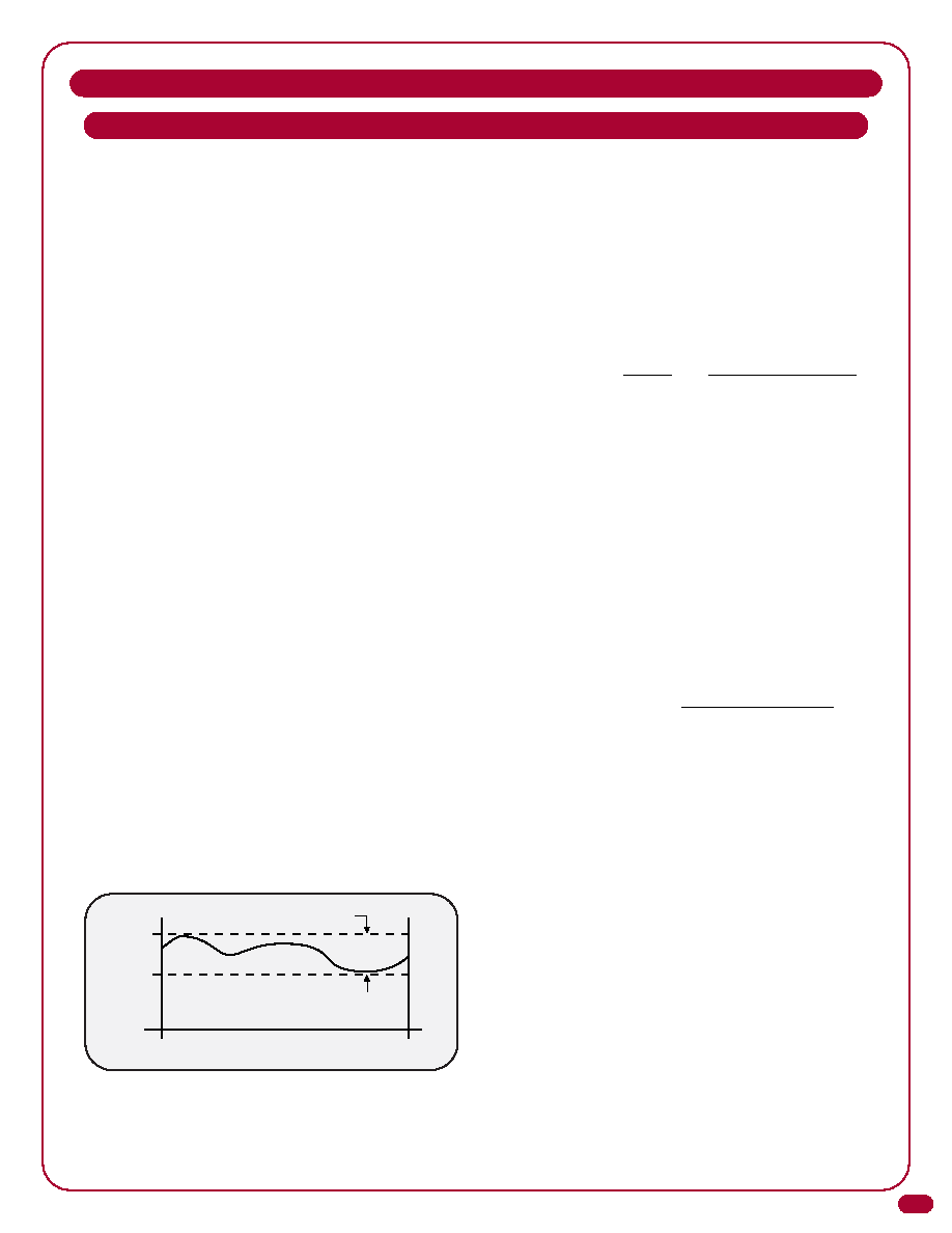
GAIN FLATNESS
Gain flatness describes the variation in an amplifier's
gain over the operating frequency range at any fixed
temperature within the operating temperature range.
As such, it does not include the variation of gain as a
function of temperature (see Gain Variation vs.
Temperature).
The gain flatness of an amplifier is measured by view-
ing the swept gain and determining the difference
between the minimum gain and the maximum gain
SPECIFICATION DEFINITIONS
Peak-to-Peak Gain Flatness
Operating Frequency Range
(Measured at one temperature)
Max. Gain
Min. Gain
F Low
F High
4
Noise Figure =
=
Si/Ni
So/No
Signal-to-noise ratio
at the amplifier input
Signal-to-noise ratio
at the amplifier output
Noise Figure = 10 Log 10
{
+1
}
Noise Temperature (Kelvin)
290 Kelvin
相關(guān)PDF資料 |
PDF描述 |
|---|---|
| AM-1571-70 | 50 MHz - 90 MHz RF/MICROWAVE NARROW BAND LOW POWER AMPLIFIER |
| AU-2A-1241 | 50 MHz - 90 MHz RF/MICROWAVE NARROW BAND LOW POWER AMPLIFIER |
| AUP-1568 | 5 MHz - 200 MHz RF/MICROWAVE WIDE BAND MEDIUM POWER AMPLIFIER |
| AUIRF1324WL | 240 A, 24 V, 0.0013 ohm, N-CHANNEL, Si, POWER, MOSFET, TO-262AA |
| AUIRF1324 | 195 A, 24 V, 0.0015 ohm, N-CHANNEL, Si, POWER, MOSFET, TO-220AB |
相關(guān)代理商/技術(shù)參數(shù) |
參數(shù)描述 |
|---|---|
| AM-157-PIN | 功能描述:射頻放大器 20-500MHz NF 7.5dB VSWR 1.50:1 RoHS:否 制造商:Skyworks Solutions, Inc. 類(lèi)型:Low Noise Amplifier 工作頻率:2.3 GHz to 2.8 GHz P1dB:18.5 dBm 輸出截獲點(diǎn):37.5 dBm 功率增益類(lèi)型:32 dB 噪聲系數(shù):0.85 dB 工作電源電壓:5 V 電源電流:125 mA 測(cè)試頻率:2.6 GHz 最大工作溫度:+ 85 C 安裝風(fēng)格:SMD/SMT 封裝 / 箱體:QFN-16 封裝:Reel |
| AM158 | 制造商:SPC Multicomp 功能描述:BRIDGE RECTIFIER 1.5A 800V 制造商:SPC Multicomp 功能描述:BRIDGE RECTIFIER, 1.5A, 800V 制造商:SPC Multicomp 功能描述:BRIDGE RECTIFIER, 1PH 1.5A 800V THD; No. of Phases:Single; Repetitive Reverse Voltage Vrrm Max:800V; Forward Current If(AV):1.5A; Forward Voltage VF Max:1V; No. of Pins:4; Diode Mounting Type:Through Hole; Body Height:5.5mm ;RoHS Compliant: Yes |
| AM158 _B0 _10001 | 制造商:PanJit Touch Screens 功能描述: |
| AM158 | 制造商:SPC Multicomp 功能描述:BRIDGE RECTIFIER 1.5A 800V |
| AM158-G | 制造商:COMCHIP 制造商全稱(chēng):Comchip Technology 功能描述:Silicon Miniature Single-Phase Bridge |
發(fā)布緊急采購(gòu),3分鐘左右您將得到回復(fù)。