- 您現(xiàn)在的位置:買賣IC網(wǎng) > PDF目錄366550 > AM79C901AVCT (Advanced Micro Devices, Inc.) HomePHY Single-Chip 1/10 Mbps Home Networking PHY PDF資料下載
參數(shù)資料
| 型號(hào): | AM79C901AVCT |
| 廠商: | Advanced Micro Devices, Inc. |
| 英文描述: | HomePHY Single-Chip 1/10 Mbps Home Networking PHY |
| 中文描述: | HomePHY單芯片的1 / 10 Mbps的家庭網(wǎng)絡(luò)物理層 |
| 文件頁(yè)數(shù): | 40/90頁(yè) |
| 文件大小: | 714K |
| 代理商: | AM79C901AVCT |
第1頁(yè)第2頁(yè)第3頁(yè)第4頁(yè)第5頁(yè)第6頁(yè)第7頁(yè)第8頁(yè)第9頁(yè)第10頁(yè)第11頁(yè)第12頁(yè)第13頁(yè)第14頁(yè)第15頁(yè)第16頁(yè)第17頁(yè)第18頁(yè)第19頁(yè)第20頁(yè)第21頁(yè)第22頁(yè)第23頁(yè)第24頁(yè)第25頁(yè)第26頁(yè)第27頁(yè)第28頁(yè)第29頁(yè)第30頁(yè)第31頁(yè)第32頁(yè)第33頁(yè)第34頁(yè)第35頁(yè)第36頁(yè)第37頁(yè)第38頁(yè)第39頁(yè)當(dāng)前第40頁(yè)第41頁(yè)第42頁(yè)第43頁(yè)第44頁(yè)第45頁(yè)第46頁(yè)第47頁(yè)第48頁(yè)第49頁(yè)第50頁(yè)第51頁(yè)第52頁(yè)第53頁(yè)第54頁(yè)第55頁(yè)第56頁(yè)第57頁(yè)第58頁(yè)第59頁(yè)第60頁(yè)第61頁(yè)第62頁(yè)第63頁(yè)第64頁(yè)第65頁(yè)第66頁(yè)第67頁(yè)第68頁(yè)第69頁(yè)第70頁(yè)第71頁(yè)第72頁(yè)第73頁(yè)第74頁(yè)第75頁(yè)第76頁(yè)第77頁(yè)第78頁(yè)第79頁(yè)第80頁(yè)第81頁(yè)第82頁(yè)第83頁(yè)第84頁(yè)第85頁(yè)第86頁(yè)第87頁(yè)第88頁(yè)第89頁(yè)第90頁(yè)

40
Am79C901A
P R E L I M I N A R Y
Auto-Negotiation goes further by providing a mes-
sage-based communication scheme called
Next
Pages
before connecting to the Link Partner.
Soft Reset Function
The PHY Control Register (TBR0) incorporates the soft
reset function (bit 15). It is a read/write register and is
self-clearing. Writing a 1 to this bit causes a soft reset.
When read, the register returns a 1 if the soft reset is
still being performed; otherwise, it is cleared to zero.
Note that the register can be polled to verify that the
soft reset has terminated
. Under normal operating con-
ditions, soft reset will be finished in 150 clock cycles.
Soft reset only resets the 10BASE-T PHY unit registers
to default values (some register bits retain their previ-
ous values). Soft reset does not reset the management
interface.
10BASE-T Loopback
The 10BASE-T PHY is capable of supporting two dif-
ferent types of loopback, referred to as internal and
external loopback.
Internal Loopback
In internal loopback, the transmitted data is returned to
the receive data bus without transmitted data appear-
ing on the network. The MAC must be programmed to
support full-duplex operation and is responsible for
comparing the transmitted data to that received. Inter-
nal loopback is accomplished by setting the
“
enable
loopback mode
”
in TBR0, bit 14, to 1.
External Loopback
External loopback is accomplished by the use of an ex-
ternal shorting plug. In this environment, the
10BASE-T PHY is left in through mode (i.e., enable
loopback mode in TBR0 = 0), the MAC in full duplex.
The transmitted data will then be looped back at the
shorting plug into the receive circuitry and driven onto
the receive data bus for the MAC to process and verify.
LED Support
The controller can support up to five LEDs. LED out-
puts LED_COL, LED_ACTIVITY, LED_LINK,
LED_SPEED, and LED_POWER allow for direct con-
nection of an LED and its supporting pull-up device.
The outputs are stretched to allow the human eye to
recognize even short events that last only several mi-
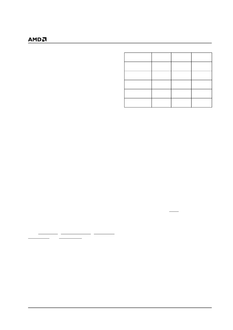
croseconds. The five LED outputs are configured as
shown in Table 11.
Table 11.
LED Default Configuration
IEEE 1149.1 (JTAG) Test Access Port
Interface
An IEEE 1149.1-compatible boundary scan Test Ac-
cess Port is provided for board-level continuity test and
diagnostics. All digital input, output, and input/output
pins are tested. The following paragraphs summarize
the IEEE 1149.1-compatible test functions imple-
mented in the controller. Refer to the IEEE 1149.1
Boundary Scan Architecture document for details.
Boundary Scan Circuit
The boundary scan test circuit requires four pins (TCK,
TMS, TDI, and TDO), defined as the Test Access Port
(TAP). It includes a finite state machine (FSM), an in-
struction register, a data register array, and a power-on
reset circuit. Internal pull-up resistors are provided for
the TDI, TCK, and TMS pins.
TAP Finite State Machine
The TAP engine is a 16-state FSM driven by the Test
Clock (TCK) and the Test Mode Select (TMS) pins. An
independent power-on reset circuit is provided to en-
sure that the FSM is in the TEST_LOGIC_RESET state
at power-up. Therefore, the TRST is not provided. The
FSM is also reset when TMS and TDI are high for five
TCK periods.
Supported Instructions
In addition to the minimum IEEE 1149.1 requirements
(BYPASS, EXTEST, and SAMPLE instructions), two
additional instructions (IDCODE and TRI_ST) are
provided to further ease board-level testing. All unused
instruction codes are reserved. See Table 12 for a sum-
mary of supported instructions.
LED Output
Indication
Driver
Mode
Open Drain
- Active Low
Open Drain
- Active Low
Open Drain
- Active Low
Open Drain
- Active Low
Open Drain
- Active Low
Pulse
Stretch
LED_COL
Collision
Enabled
LED_ACTIVITY
Activity
Enabled
LED_LINK
Link
Not
applicable
Not
applicable
Not
applicable
LED_SPEED
Speed
LED_POWER
Power
相關(guān)PDF資料 |
PDF描述 |
|---|---|
| AM79C901AVI | HomePHY Single-Chip 1/10 Mbps Home Networking PHY |
| AM79C901AVIT | HomePHY Single-Chip 1/10 Mbps Home Networking PHY |
| AM79C90 | CMOS Local Area Network Controller for Ethernet (C-LANCE) |
| AM79C90JC | CMOS Local Area Network Controller for Ethernet (C-LANCE) |
| AM79C90JCTR | KPTC6CG10-6P |
相關(guān)代理商/技術(shù)參數(shù) |
參數(shù)描述 |
|---|---|
| AM79C901AVI | 制造商:AMD 制造商全稱:Advanced Micro Devices 功能描述:HomePHY Single-Chip 1/10 Mbps Home Networking PHY |
| AM79C901AVIT | 制造商:AMD 制造商全稱:Advanced Micro Devices 功能描述:HomePHY Single-Chip 1/10 Mbps Home Networking PHY |
| AM79C90JC | 制造商:Rochester Electronics LLC 功能描述: |
| AM79C90JC-G | 制造商:Rochester Electronics LLC 功能描述: |
| AM79C90JCTR | 制造商:AMD 制造商全稱:Advanced Micro Devices 功能描述:CMOS Local Area Network Controller for Ethernet (C-LANCE) |
發(fā)布緊急采購(gòu),3分鐘左右您將得到回復(fù)。