- 您現在的位置:買賣IC網 > PDF目錄366552 > AM8530 (Advanced Micro Devices, Inc.) Serial Communications Controller PDF資料下載
參數資料
| 型號: | AM8530 |
| 廠商: | Advanced Micro Devices, Inc. |
| 英文描述: | Serial Communications Controller |
| 中文描述: | 串行通信控制器 |
| 文件頁數: | 136/194頁 |
| 文件大小: | 797K |
| 代理商: | AM8530 |
第1頁第2頁第3頁第4頁第5頁第6頁第7頁第8頁第9頁第10頁第11頁第12頁第13頁第14頁第15頁第16頁第17頁第18頁第19頁第20頁第21頁第22頁第23頁第24頁第25頁第26頁第27頁第28頁第29頁第30頁第31頁第32頁第33頁第34頁第35頁第36頁第37頁第38頁第39頁第40頁第41頁第42頁第43頁第44頁第45頁第46頁第47頁第48頁第49頁第50頁第51頁第52頁第53頁第54頁第55頁第56頁第57頁第58頁第59頁第60頁第61頁第62頁第63頁第64頁第65頁第66頁第67頁第68頁第69頁第70頁第71頁第72頁第73頁第74頁第75頁第76頁第77頁第78頁第79頁第80頁第81頁第82頁第83頁第84頁第85頁第86頁第87頁第88頁第89頁第90頁第91頁第92頁第93頁第94頁第95頁第96頁第97頁第98頁第99頁第100頁第101頁第102頁第103頁第104頁第105頁第106頁第107頁第108頁第109頁第110頁第111頁第112頁第113頁第114頁第115頁第116頁第117頁第118頁第119頁第120頁第121頁第122頁第123頁第124頁第125頁第126頁第127頁第128頁第129頁第130頁第131頁第132頁第133頁第134頁第135頁當前第136頁第137頁第138頁第139頁第140頁第141頁第142頁第143頁第144頁第145頁第146頁第147頁第148頁第149頁第150頁第151頁第152頁第153頁第154頁第155頁第156頁第157頁第158頁第159頁第160頁第161頁第162頁第163頁第164頁第165頁第166頁第167頁第168頁第169頁第170頁第171頁第172頁第173頁第174頁第175頁第176頁第177頁第178頁第179頁第180頁第181頁第182頁第183頁第184頁第185頁第186頁第187頁第188頁第189頁第190頁第191頁第192頁第193頁第194頁
Register Description
AMD
6–26
6.2.13
Write Register 12 (Lower Byte of Baud Rate
Generator T ime Constant)
WR12 contains the lower byte of the time constant for the baud rate generator. The time
constant can be changed at any time, but the new value does not take effect until the next
time the time constant is loaded into the down counter. No attempt is made to synchro-
nize the loading of the time constant into WR12 and WR13 with the clock driving the
down counter. For this reason, it is advisable to disable the baud rate generator while the
new time constant is loaded into WR12 and WR13. Ordinarily, this is done anyway to pre-
vent a load of the down counter between the writing of the upper and lower bytes of the
time constant.
The formula for determining the appropriate time constant for a given baud is shown be-
low with the desired rate in bits per second and the BR clock period in seconds. This for-
mula is derived because the counter decrements from N down to ‘0’-plus-one-cycle for
reloading the time constant and is then fed to a toggle flip-flop to make the output a
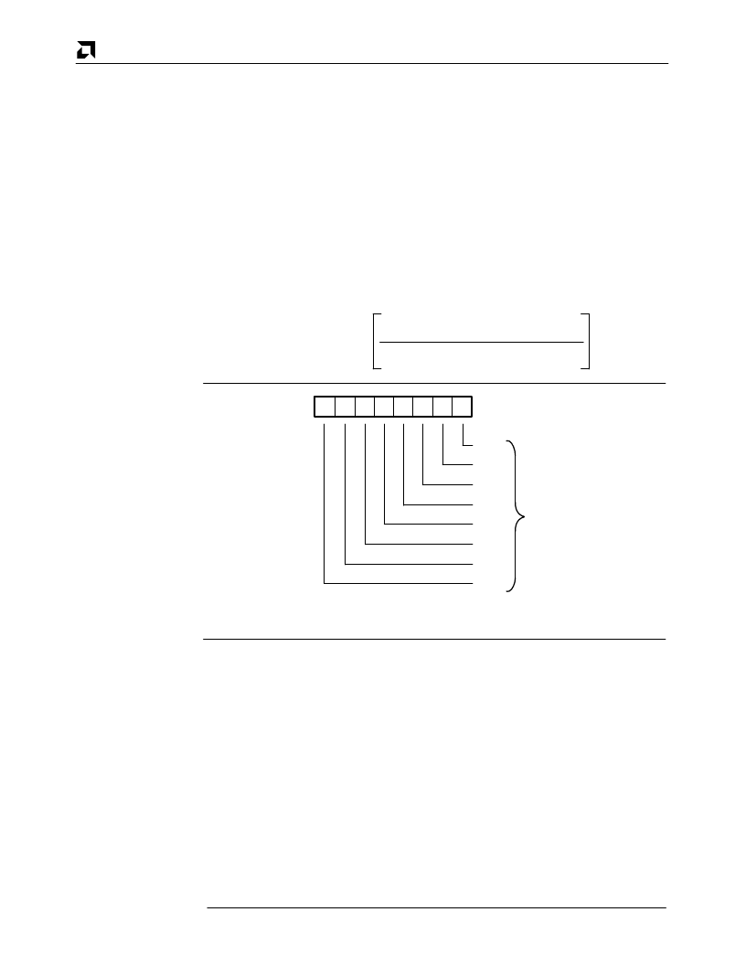
square wave. Bit positions for WR12 are shown in Figure 6–14.
Time Constant =
1
2
(Desired Rate)
(Baud Rate)
–2
D
7
D
6
D
5
D
4
D
3
D
2
D
1
D
0
TC
3
TC
4
TC
5
TC
6
TC
0
TC
1
TC
2
TC
7
Lower Byte of
Time Constant
Figure 6–14. Write Register 12
6.2.14
Write Register 13 (Upper Byte of Baud Rate
Generator T ime Constant)
WR13 contains the upper byte of the time constant for the baud rate generator. Bit posi-
tions for WR13 are shown in Figure 6–15.
相關PDF資料 |
PDF描述 |
|---|---|
| AM8530H | Serial Communications Controller |
| AM85C30-10PC | Enhanced Serial Communications Controller |
| Am85C30 | Serial Communications Controller |
| AM85C30 | Enhanced Serial Communications Controller |
| AM85C30-8PC | Enhanced Serial Communications Controller |
相關代理商/技術參數 |
參數描述 |
|---|---|
| AM8530ADC | 制造商:未知廠家 制造商全稱:未知廠家 功能描述:Communications Controller |
| AM8530ADCB | 制造商:未知廠家 制造商全稱:未知廠家 功能描述:Communications Controller |
| AM8530AJC | 制造商:未知廠家 制造商全稱:未知廠家 功能描述:Communications Controller |
| AM8530APC | 制造商:未知廠家 制造商全稱:未知廠家 功能描述:Communications Controller |
| AM8530DC | 制造商:未知廠家 制造商全稱:未知廠家 功能描述:Communications Controller |
發(fā)布緊急采購,3分鐘左右您將得到回復。