- 您現(xiàn)在的位置:買賣IC網(wǎng) > PDF目錄362330 > AN135 Sensor Circuits and Digitally Controlled Potentiometers PDF資料下載
參數(shù)資料
| 型號: | AN135 |
| 元件分類: | 數(shù)字電位計 |
| 英文描述: | Sensor Circuits and Digitally Controlled Potentiometers |
| 中文描述: | 傳感器電路和數(shù)字控制電位器 |
| 文件頁數(shù): | 4/5頁 |
| 文件大小: | 47K |
| 代理商: | AN135 |
Xicor Application Note
AN135-4
AN135
pressure sensor that is compatible (thanks to DCP1 and
2) with full automation of the calibration process, is very
low in total power draw (< 1 milliampere, most of which
goes to transducer excitation), and (equally important) is
low in cost.
PRTD SIGNAL CONDITIONING CIRCUIT
Among
temperature
resistance temperature detector (PRTD) is generally
accepted as the ‘gold standard’. PRTDs are ubiquitous
and find wide application in the aviation, environmental,
industrial, and scientific instrumentation areas. The
circuit in Figure 5 uses the PRTD in a bridge circuit
whose output is amplified by a high performance
instrumentation amplifier (IA). Amongst the problems
associated with this traditional approach is the lack of
variablility to account for sensor variations, lack of a
linearization scheme, and the high cost of the
instrumentation amplifier.
transducers,
the
platinum
The PRTD temperature response consists of resistance
variations of the order of only tenths of ohms/°C. Hence
strict attention must be paid to the effects of transducer
lead wire resistance. The magnitude of the excitation
current must also be severely limited, otherwise
excessive I
R PRTD power dissipation will cause
unacceptably large self-heating measurement errors.
Low excitation currents and small resistance changes
combine to mean that the signal developed by the PRTD
will typically be of the order of tens of μV/°C generating
a requirement for stable high gain DC amplification in
the signal chain. In addition, the PRTD temperature
coefficient
is
only
‘reasonably’
temperature and, as a result, the PRTD’s response is
significantly nonlinear. The accurate measurement of
temperature over a wide range depends on the
provision for linearization of the PRTD signal. These
design considerations are incorporated in the circuit of
Figure 6 and result in a precision thermometer with
2
invariant
with
output span of –1V to +3.5V corresponding to a
temperature range of –100 to +350°C. The maximum
error over this span can be adjusted to ±0.02°C at 0°C
and ±0.05°C elsewhere.
Current excitation (approximately 250μA) for the PRTD
is sourced by the 2.5V voltage reference VR1 via R1.
The 256 tap digitally controlled potentiometer DCP1
provides for automated adjustment of the thermometer
scale factor and span. A1 is a noninverting amplifier with
a gain of 100 which scales up the raw 100μV/°C PRTD
temperature signal to 0.01V/°C. The DCP2 network
implements a high resolution zero adjustment. Each
increment in DCP2’s setting will result in a 200μV shift in
Al’s output which is equivalent to a 0.02°C zero
adjustment. The symmetry of the R6-R9 network
surrounding DCP2 causes zero adjustment to have no
effect on A1’s gain and therefore no effect on the
thermometer’s span/scale factor. Likewise, span
adjustments via changes in the VR1 reference allow no
interaction between DCP1 and the zero calibration
established by DCP2.
Positive feedback provided by R2 linearizes the
thermometer’s response curve by providing a Thevenin
equivalent of a negative amplifier input resistance of –
2064 ohms in parallel with R1. This introduces a positive
gain slope (roughly +0.016%/°C) which effectively
cancels the tendency of the PRTD temperature
coefficient to decline with increasing temperature. The
result is better than a factor of 100 improvement in
linearity over the raw PRTD response.
The net result of the combination of A1 and the
associated circuit is a signal conditioning, precision
temperature sensor that is compatible (thanks to DCP1
and 2) with full automation of the calibration process,
low in total power draw, and low in cost.
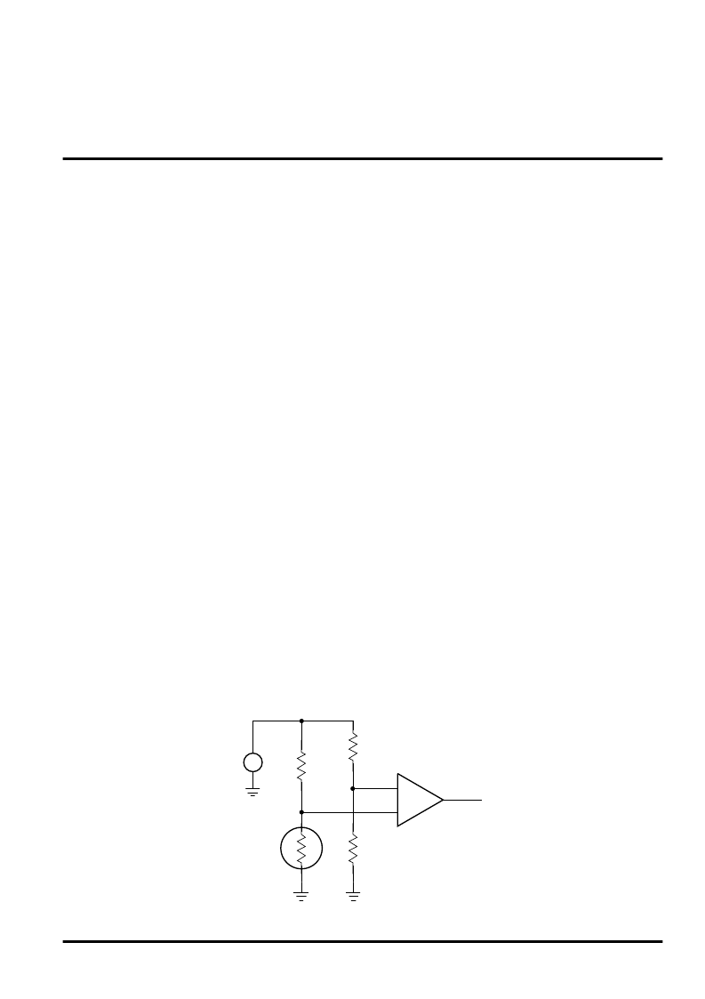
Figure 5. PRTD Sensor Circuit – Basic
V
BIAS
V
OUT
∝
°CV
PRTD
IA
相關(guān)PDF資料 |
PDF描述 |
|---|---|
| AN2012S | Optoelectronic |
| AN2012SB | Optoelectronic |
| AN201 | JT 22C 22#22D PIN RECP |
| AN2034FAP | Video Camera Circuit |
| AN2035FAQ | Optoelectronic |
相關(guān)代理商/技術(shù)參數(shù) |
參數(shù)描述 |
|---|---|
| AN1354 | 制造商:未知廠家 制造商全稱:未知廠家 功能描述:SINGLE-PHASE INDUCTION MOTOR DRIVE FOR REFRIGERATOR COMPRESSOR APPLICATION |
| AN1358 | 制造商:PANASONIC 制造商全稱:Panasonic Semiconductor 功能描述:Dual Operational Amplifiers |
| AN1358S | 制造商:Panasonic Industrial Company 功能描述:IC |
| AN1358S(AN6562S) | 制造商:未知廠家 制造商全稱:未知廠家 功能描述:Voltage-Feedback Operational Amplifier |
| AN1358S-E1 | 制造商:Panasonic Industrial Company 功能描述:IC |
發(fā)布緊急采購,3分鐘左右您將得到回復(fù)。