- 您現(xiàn)在的位置:買賣IC網(wǎng) > PDF目錄362338 > AN79N24 Negative Fixed Voltage Regulator PDF資料下載
參數(shù)資料
| 型號: | AN79N24 |
| 英文描述: | Negative Fixed Voltage Regulator |
| 中文描述: | 負(fù)固定電壓穩(wěn)壓器 |
| 文件頁數(shù): | 6/10頁 |
| 文件大小: | 213K |
| 代理商: | AN79N24 |
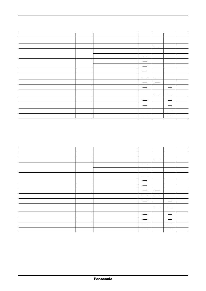
AN79Nxx Series
Voltage Regulators
6
I
Electrical Characteristics at
T
a
=
25
°
C (continued)
AN79N12 (
12V type)
AN79N15 (
15V type)
V
O
V
O
V
V
T
j
=
25
°
C
V
I
=
17.5 to
30V, I
O
=
5 to 200mA
V
I
=
17.5
to
30V, T
j
=
25
°
C
V
I
=
18
to
28V, T
j
=
25
°
C
REG
IN
mV
mV
REG
L
mV
I
O
=
1
to
300mA, T
j
=
25
°
C
I
O
=
5
to
200mA, T
j
=
25
°
C
T
j
=
25
°
C
V
I
=
17.5
to
30V, T
j
=
25
°
C
I
O
=
5
to
200mA, T
j
=
25
°
C
f
=
10Hz
to
100kHz
V
I
=
18
to
28V, I
O
=
50mA,
f
=
120Hz
I
O
=
200mA, T
j
=
25
°
C
V
I
=
35V, T
j
=
25
°
C
T
j
=
25
°
C
I
O
=
5mA
mV
mA
I
Bias
mA
I
Bias(IN)
I
Bias(L)
V
no
mA
μ
V
dB
RR
V
V
DIF(min)
mA
I
O(Short)
I
O(Peak)
V
O
/T
a
mA
mV/
°
C
15.6
15.75
15
80
50
16
11
25
3
375
0.5
0.1
240
120
5
56
14.4
14.25
1.1
10
500
0.9
10
Parameter
Symbol
Conditions
Min
Typ
Max
Output voltage
Output voltage tolerance
Line regulation
Load regulation
Note 1) The specified condition T
j
=
25
°
C means that the test should be carried out within so short a test time (within 10ms) that the
characteristic value drift due to the chip junction temperature rise can be ignored.
Note 2) Unless otherwise specified, V
I
=
23V, I
O
=
100mA, C
I
=
2
μ
F, C
O
=
1
μ
F and T
j
=
0 to 125
°
C
Bias current
Bias current fluctuation to input
Bias current fluctuation to load
Output noise voltage
Ripple rejection ratio
Minimum input/output voltage difference
Output short-circuit current
Peak output current
Output voltage temperature coefficient
Unit
V
O
V
O
V
V
T
j
=
25
°
C
V
I
=
14.5 to
30V, I
O
=
5 to 200mA
V
I
=
14.5
to
30V, T
j
=
25
°
C
V
I
=
15
to
25V, T
j
=
25
°
C
REG
IN
mV
mV
REG
L
mV
I
O
=
1
to
300mA, T
j
=
25
°
C
I
O
=
5
to
200mA, T
j
=
25
°
C
T
j
=
25
°
C
V
I
=
14.5
to
30V, T
j
=
25
°
C
I
O
=
5
to
200mA, T
j
=
25
°
C
f
=
10Hz
to
100kHz
V
I
=
15
to
25V, I
O
=
50mA,
f
=
120Hz
I
O
=
200mA, T
j
=
25
°
C
V
I
=
35V, T
j
=
25
°
C
T
j
=
25
°
C
I
O
=
5mA
mV
mA
I
Bias
mA
I
Bias(IN)
I
Bias(L)
V
no
mA
μ
V
dB
RR
V
V
DIF(min)
mA
I
O(Short)
I
O(Peak)
V
O
/T
a
mA
mV/
°
C
12.5
12.6
12
80
50
15
10
25
3
300
0.5
0.1
240
120
5
57
11.5
11.4
1.1
10
500
0.8
10
Parameter
Symbol
Conditions
Min
Typ
Max
Output voltage
Output voltage tolerance
Line regulation
Load regulation
Note 1) The specified condition T
=
25
°
C means that the test should be carried out within so short a test time (within 10ms) that the
characteristic value drift due to the chip junction temperature rise can be ignored.
Note 2) Unless otherwise specified, V
I
=
19V, I
O
=
100mA, C
I
=
2
μ
F, C
O
=
1
μ
F and T
j
=
0 to 125
°
C
Bias current
Bias current fluctuation to input
Bias current fluctuation to load
Output noise voltage
Ripple rejection ratio
Minimum input/output voltage difference
Output short-circuit current
Peak output current
Output voltage temperature coefficient
Unit
相關(guān)PDF資料 |
PDF描述 |
|---|---|
| AN79N05 | Negative Fixed Voltage Regulator |
| AN79N07 | Negative Fixed Voltage Regulator |
| AN79N09 | Negative Fixed Voltage Regulator |
| AN8000MS | 情報(bào)?通信用 - 攜帯電話 |
| AN8013 | |
相關(guān)代理商/技術(shù)參數(shù) |
參數(shù)描述 |
|---|---|
| AN7C31BH | 制造商:INTEL 制造商全稱:Intel Corporation 功能描述:CHMOS SINGLE-CHIP 8-BIT MICROCONTROLLER |
| AN7C51BH | 制造商:INTEL 制造商全稱:Intel Corporation 功能描述:CHMOS SINGLE-CHIP 8-BIT MICROCONTROLLER |
| AN7H20A | 制造商:undefined 功能描述: |
| AN7X150SR | 制造商:FACOM 功能描述:SLOT SCREWDRIVER NON-SPARKING 150X7 |
| AN8000 | 制造商:PANASONIC 制造商全稱:Panasonic Semiconductor 功能描述:3-pin Positive Output Low Dropout Voltage Regulator 50mA Type |
發(fā)布緊急采購,3分鐘左右您將得到回復(fù)。