- 您現(xiàn)在的位置:買賣IC網(wǎng) > PDF目錄362395 > AQY210LSZ GU (General Use) Type SOP Series 1-Channel (Form A) Current Limit Function 4-Pin Type PDF資料下載
參數(shù)資料
| 型號: | AQY210LSZ |
| 英文描述: | GU (General Use) Type SOP Series 1-Channel (Form A) Current Limit Function 4-Pin Type |
| 中文描述: | 顧(一般使用)型SOP系列單通道(表格A)電流限制功能4引腳型 |
| 文件頁數(shù): | 3/3頁 |
| 文件大?。?/td> | 49K |
| 代理商: | AQY210LSZ |
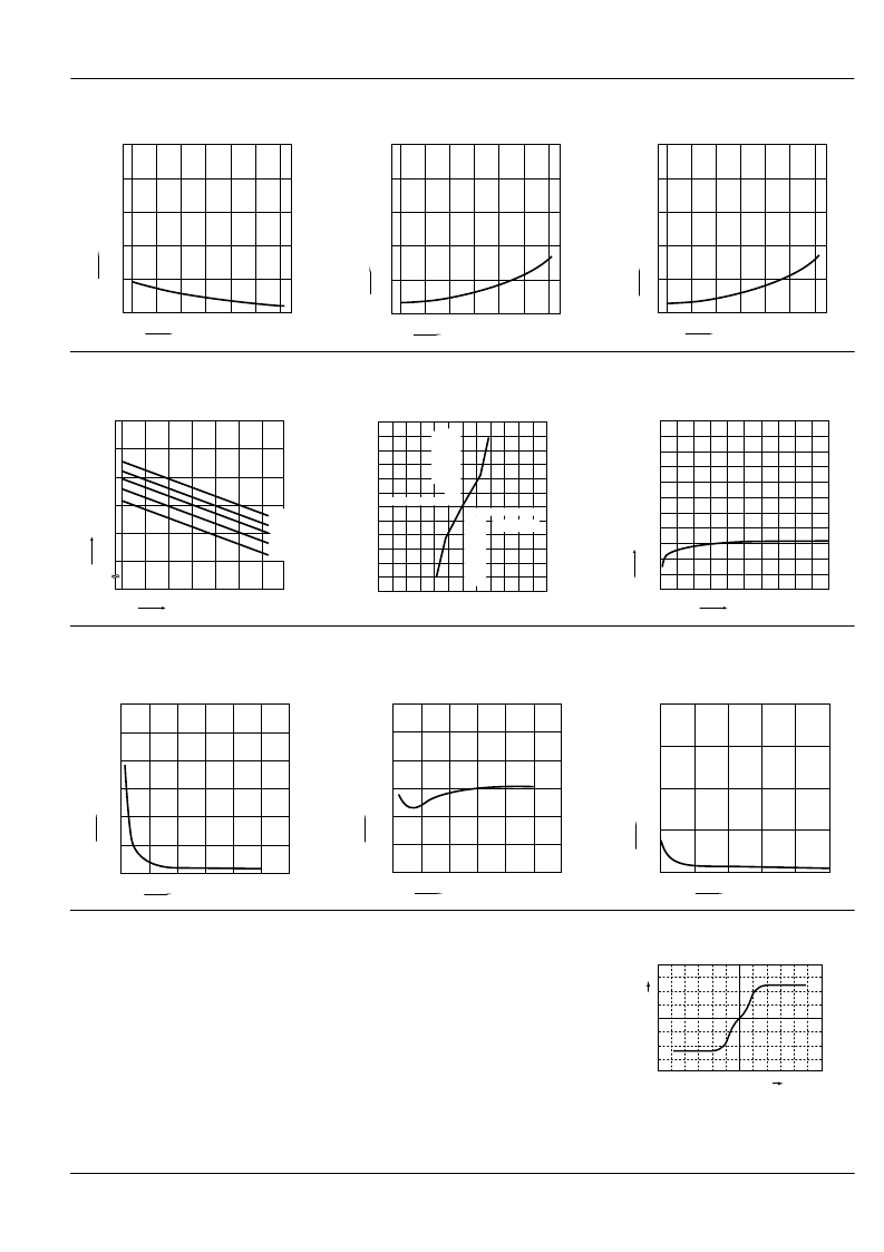
AQY210LS
4. Turn off time vs. ambient temperature char-
acteristics
LED current: 5 mA; Load voltage: Max.(DC);
Continuous load current: Max.(DC)
0.5
5. LED operate current vs. ambient tempera-
ture characteristics
Load voltage: Max.(DC);
Continuous load current: Max.(DC)
5
6. LED turn off current vs. ambient temperature
characteristics
Load voltage: Max.(DC);
Continuous load current: Max.(DC)
5
Ambient temperature,
°
C
T
0
0.1
0.2
0.3
0.4
–40
–20
0
20
40
60
8085
Ambient temperature,
°
C
L
0
1
2
3
4
–40
–20
0
20
40
60
80 85
Ambient temperature,
°
C
L
0
1
2
3
4
–40
–20
0
20
40
60
80 85
7. LED dropout voltage vs. ambient tempera-
ture characteristics
LED current: 5 to 50 mA
8. Voltage vs. current characteristics of output
at MOS portion
Measured portion: between terminals 3 and 4;
Ambient temperature: 25
°
C
77
°
F
9. Off state leakage current
Measured portion: between terminals 3 and 4;
Ambient temperature: 25
°
C
77
°
F
0
–40 –20
20
40
60
8085
Ambient temperature,
°
C
L
50mA
30mA
10mA
5mA
1.5
1.4
1.3
1.2
1.1
1.0
0
5
3
1
–100
–60
–80
–20
–40
2
4
–5
–3
–1
100
80
60
40
20
–2
–4
Voltage, V
C
Load voltage, V
O
20
0
60
40
80
100
10
–3
10
–6
10
–9
10
–12
10. LED forward current vs. turn on time char-
acteristics
Measured portion: between terminals 3 and 4;
Load voltage: Max.(DC); Continuous load current:
Max.(DC); Ambient temperature: 25
1.2
°
C
77
°
F
11. LED forward current vs. turn off time char-
acteristics
Measured portion: between terminals 3 and 4;
Load voltage: Max.(DC); Continuous load current:
Max.(DC); Ambient temperature: 25
0.12
°
C
77
°
F
12. Applied voltage vs. output capacitance
characteristics
Measured portion: between terminals 3 and 4;
Frequency: 1 MHz; Ambient temperature: 25
°
C
77
°
F
LED forward current, mA
T
0
0.2
0.4
0.6
0.8
1.0
10
0
20
30
40
50
60
LED forward current, mA
T
0
0.02
0.04
0.08
0.06
10
0
20
30
40
0.10
50
60
Applied voltage, V
O
0
50
100
10
20
30
40
50
150
200
0
What is current limit
When a load current reaches the speci-
fied output control current, a current limit
function works against the load current to
keep the current a constant value.
The current limit circuit built into the Pho-
toMOS relay thus controls the instanta-
neous load current to effectively ensure
circuit safety.
This safety feature protects circuits down-
stream of the PhotoMOS relay against
over-current.
But, if the current-limiting feature is used
longer than the specified time, the Photo-
MOS relay can be destroyed. Therefore,
set the output loss to the max. rate or less.
Comparison of output voltage and output
current characteristics
V-I Characteristics
O
Output voltage
5/7/2001
All Rights Reserved, Copyright Matsushita Electric Works, Ltd.
Go To Online Catalog
相關(guān)PDF資料 |
PDF描述 |
|---|---|
| AQY274 | PD Type 1- channel (Form A) Type |
| AQY275 | PD Type 1- channel (Form A) Type |
| AQY275A | PD Type 1- channel (Form A) Type |
| AQY275AX | PD Type 1- channel (Form A) Type |
| AQY275AZ | PD Type 1- channel (Form A) Type |
相關(guān)代理商/技術(shù)參數(shù) |
參數(shù)描述 |
|---|---|
| AQY210S | 功能描述:固態(tài)繼電器-PCB安裝 120MA 350V 6PIN SPST RoHS:否 制造商:Omron Electronics 控制電壓范圍: 負(fù)載電壓額定值:40 V 負(fù)載電流額定值:120 mA 觸點(diǎn)形式:1 Form A (SPST-NO) 輸出設(shè)備:MOSFET 封裝 / 箱體:USOP-4 安裝風(fēng)格:SMD/SMT |
| AQY-210S | 制造商:Panasonic 功能描述:Bulk |
| AQY210S | 制造商:Panasonic Electric Works 功能描述:PhotoMOS Relay Switch Function:SPST-NO |
| AQY210S1Y | 功能描述:固態(tài)繼電器-PCB安裝 350v 120mA SOP Form A Norm-Open RoHS:否 制造商:Omron Electronics 控制電壓范圍: 負(fù)載電壓額定值:40 V 負(fù)載電流額定值:120 mA 觸點(diǎn)形式:1 Form A (SPST-NO) 輸出設(shè)備:MOSFET 封裝 / 箱體:USOP-4 安裝風(fēng)格:SMD/SMT |
| AQY210ST | 制造商:Panasonic 功能描述:PN may be NE CE |
發(fā)布緊急采購,3分鐘左右您將得到回復(fù)。