- 您現(xiàn)在的位置:買賣IC網(wǎng) > PDF目錄1902 > AS2540-T (ams)IC TELEPHONE CMOS MULTIFU 28SOIC PDF資料下載
參數(shù)資料
| 型號: | AS2540-T |
| 廠商: | ams |
| 文件頁數(shù): | 15/19頁 |
| 文件大小: | 0K |
| 描述: | IC TELEPHONE CMOS MULTIFU 28SOIC |
| 標準包裝: | 1,500 |
| 系列: | * |
Data Sheet AS2540
austriamicrosystems
Revision 3.1
Page 4 of 18
Functional Description
Modes of operation
There are 4 possible modes:
Idle Mode
Manual hook-switch and electronic hook-switch (e.g. relay)
is open (MHS
∩ EHS = logical 0), no ring signal is applied,
the oscillator is stopped, signalling via the serial interface
is not possible.
Ringing Mode
AS2540 is supplied via the ring capacitor and external
path, manual hook -switch and electronic hook-switch is
open (MHS
∩ EHS = logical 0), the oscillator is running, a
valid incoming ringing is signalled via the serial interface to
the CPU. If the CPU does not reply the AS2540 switches
into backup mode and sends a ring melody to the MO
output.
Backup Mode
Manual hook-switch and/or electronic hook-switch is closed
(MHS
∪ EHS = logical 1), AS2540 is supplied with line
current, the oscillator is running, the keyscan is enabled
and the handset path is switched on, signalling via the
serial interface is possible. After AS2540 has started
dialling in backup mode, he must not be interrupted any
more in order to ensure consistent dialling. A mode
transition BM -> MPM is only possible before AS2540 has
started dialling digits independently.
Main Power Mode
Manual hook-switch and/or electronic hook-switch is
closed, AS2540 is supplied with line current (MHS
∪ EHS
= logical 1), the oscillator is running, the keyscan is
disabled, AS2540 is controlled via the serial interface,
handset path or monitor path or modem path is on,
signalling via the serial interface is possible.
Select Operation Mode
Command Message
Switches ON
Switches OFF
<SetHandsetPath>
SROH
SROT & STIT
<SetModemPath>
SROT & STIT
<SetMonitorPath>
SROH & SROT
STIT
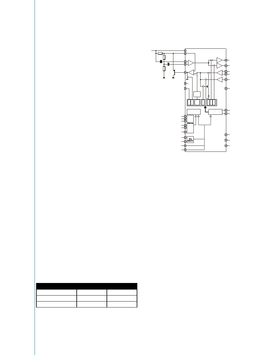
Example Main Power Mode
LS
ROH
ROT
M1
M2
TIT
AGND
Line
LI
RI
STB
CS
CI
DPn
C1
C2
C3
R1
R2
MODE
RFD
-2dB
+6dB
+2dB
Mask
DTMF-
generator
DIALLER
UART
ST
IT
SR
O
H
SR
O
T
SM
U
TE
Di
a
l
Di
g
it
SM
A
SK
SD
P
n
MO
RxD
TxD
VDD
EHS
MHS
VSS
OSC
Start-up in backup mode
As soon as AS2540 is supplied with line current, the
external Vdd capacitor will be charged up via the LI and
VDD pin and after the Vdd voltage has reached the
operating level, the handset path of the speech circuit is
switched on. This off-hook status is also signalled to the
internal logic via the MHS or EHS pin in order to start the
pinscan and subsequently set the country specific modes.
Additionally a <LineEvent> message is sent to the CPU.
Start-up in ring mode
When a ringing signal is applied to the line, Vdd of AS2540
is charged up via an external path. After Vdd has reached
the operating voltage the oscillator starts and AS2540
discriminates the ring frequency. After a valid ring
frequency is applied on the RFD pin, the logic sends a
<LineEvent> message is sent to the CPU and a watchdog
timer is started. When the <LineEvent> message is not quit
by the CPU before the watchdog timer has finished the
countdown, AS2540 changes into backup mode and sends
out a melody via the MO pin.
DC conditions
The normal operating mode is from 15mA to 100mA. An
operating mode with reduced performance is from 5mA to
15mA. In the line hold range from 0mA to 5mA the device
is in a power down mode and the voltage at LI is reduced
to a maximum of 3.5V
ams
AG
Technical
content
still
valid
相關(guān)PDF資料 |
PDF描述 |
|---|---|
| AS8002-AQFP | IC CURRENT MEASURE SOLAR 16VQFN |
| AS8501-ASOT | IC CURRENT MEASURE SOLAR 16-SOIC |
| AS8510-ASST | IC BATTERY MANAGEMENT 20-SSOP |
| AS8530-ASOT-002-500 | IC TXRX LIN COMPANION 8-SOIC |
| AS8530A-ASOT-500 | IC SYSTEM BASIS CHIP 8-SOIC |
相關(guān)代理商/技術(shù)參數(shù) |
參數(shù)描述 |
|---|---|
| AS2540TR | 制造商:ams 功能描述:IC TELEPHONE CMOS MULTIFU 28SOIC 制造商:ams 功能描述:T&R / SOIC 28 |
| AS25490FLF | 制造商:TT Electronics / IRC 功能描述:AS25490FLF |
| AS25490HLF | 制造商:TT Electronics / IRC 功能描述:AS25490HLF |
| AS25490JLF | 制造商:TT Electronics / IRC 功能描述:AS25490JLF |
| AS25491FLF | 制造商:TT Electronics / IRC 功能描述:AS25491FLF |
發(fā)布緊急采購,3分鐘左右您將得到回復。