- 您現(xiàn)在的位置:買賣IC網(wǎng) > PDF目錄223396 > ASMT-QWBE-NHLLE SINGLE COLOR LED, COOL WHITE, 2.4 mm PDF資料下載
參數(shù)資料
| 型號(hào): | ASMT-QWBE-NHLLE |
| 元件分類: | LED |
| 英文描述: | SINGLE COLOR LED, COOL WHITE, 2.4 mm |
| 封裝: | 3.20 X 2.80 MM, 1.90 MM HEIGHT, ROHS COMPLIANT, PLASTIC, SMT, LCC-4 |
| 文件頁數(shù): | 3/10頁 |
| 文件大?。?/td> | 155K |
| 代理商: | ASMT-QWBE-NHLLE |
2
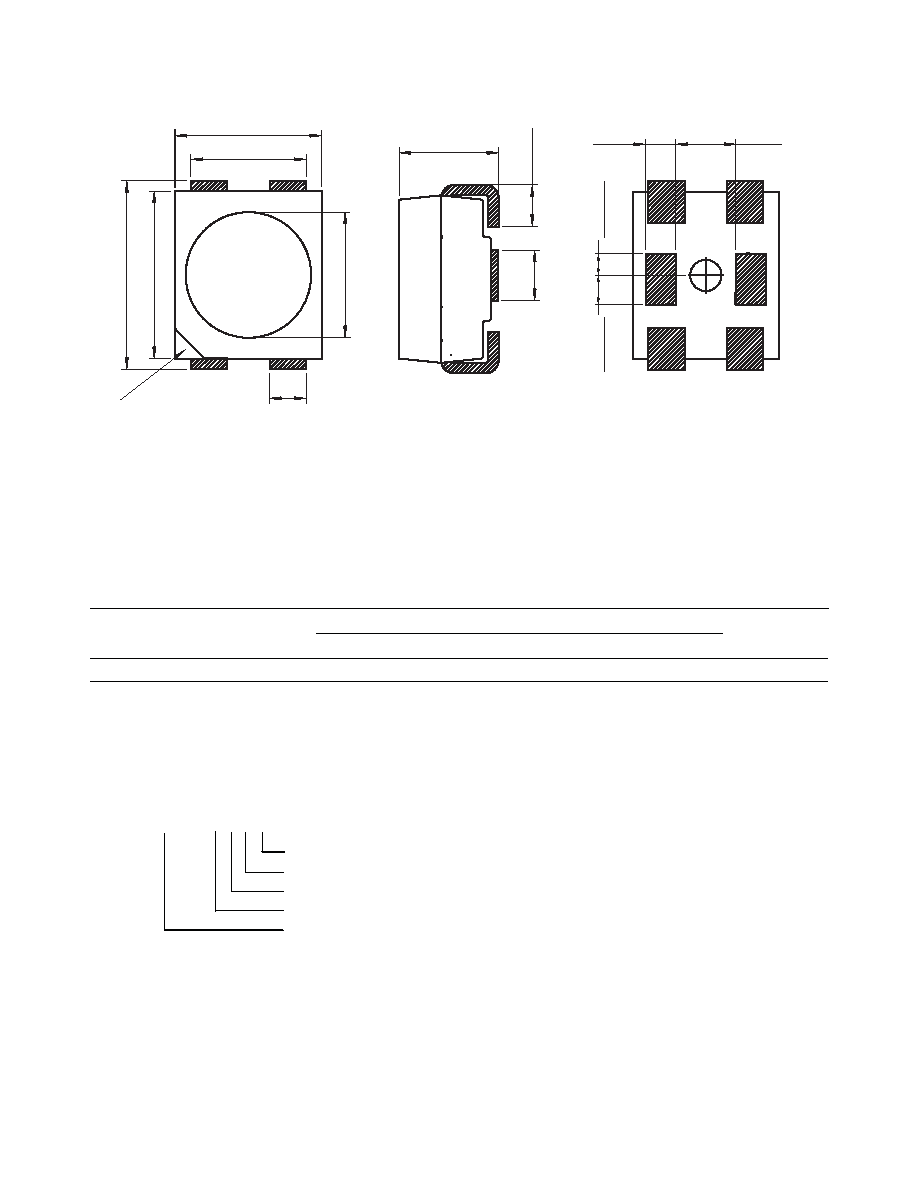
3.6
±
0.2
3.2
±
0.2
2.8 ± 0.2
2.2 ± 0.2
1.9 ± 0.2
0.6 ± 0.3
C
AA
0.79
±
0.3
CATHODE
MARKING
2.4
1.15 ± 0.2
0.41
(TYP
.)
0.56
(TYP
.)
0.97
Package Drawing
Figure 1. Package Drawing
Table 1. Device Selection Guide (TJ = 25 °C)
Color
Part Number
Luminous Flux,
)V[1] (lm)
Dice Technology
Min. Flux (lm)
Typ. Flux (lm)
Max. Flux (lm)
Test Current (mA)
Cool White
ASMT-QWBE-NFH0E
15.0
19.5
33.0
150
InGaN
Notes:
1.
)V is the total luminous ux output as measured with an integrating sphere at mono pulse conditions.
2. Tolerance = ±12%
Part Numbering System
Notes:
1. All dimensions in millimeters
2. Lead polarity as shown in gure 13.
3. Terminal nish: Ag plating.
4. Encapsulation material: silicone resin.
A S M T - Q X1B E – N X 2 X 3 X 4 X 5
Packaging Option
Colour Bin Selection
Max. Flux Bin Selection
Min. Flux Bin Selection
Color
W - Cool White
相關(guān)PDF資料 |
PDF描述 |
|---|---|
| ASMT-QWBE-NLLME | SINGLE COLOR LED, COOL WHITE, 2.4 mm |
| ASMT-QWBE-N0BKE | SINGLE COLOR LED, COOL WHITE, 2.4 mm |
| ASMT-QWBE-N0CEE | SINGLE COLOR LED, COOL WHITE, 2.4 mm |
| ASMT-QWBE-N0CME | SINGLE COLOR LED, COOL WHITE, 2.4 mm |
| ASMT-QWBE-N0JAE | SINGLE COLOR LED, COOL WHITE, 2.4 mm |
相關(guān)代理商/技術(shù)參數(shù) |
參數(shù)描述 |
|---|---|
| ASMT-QWBF-NKL0E | 功能描述:大功率LED - 白色 Cool White 0.5 Watt RoHS:否 制造商:Cree, Inc. 照明顏色:Cool White 顏色溫度:5000 K 光通量:280 lm 顯示角:125 deg 正向電流:700 mA 正向電壓:2.9 V 安裝風(fēng)格:SMD/SMT 系列:XMLBWW 封裝:Reel |
| ASMT-QWBF-NKLCE | 功能描述:ASMT-QWBF-NKLCE 制造商:broadcom limited 系列:* 零件狀態(tài):過期 標(biāo)準(zhǔn)包裝:1 |
| ASMT-QWBF-NKLFE | 功能描述:ASMT-QWBF-NKLFE 制造商:broadcom limited 系列:* 零件狀態(tài):過期 標(biāo)準(zhǔn)包裝:1 |
| ASMT-QWBG-NFH0E | 功能描述:大功率LED - 白色 White, 4000 - 8000K 48lm, CRI85, 150mA RoHS:否 制造商:Cree, Inc. 照明顏色:Cool White 顏色溫度:5000 K 光通量:280 lm 顯示角:125 deg 正向電流:700 mA 正向電壓:2.9 V 安裝風(fēng)格:SMD/SMT 系列:XMLBWW 封裝:Reel |
| ASMT-QWBG-NFHAE | 功能描述:大功率LED - 白色 Cool White, 8000K 48lm, CRI85, 150mA RoHS:否 制造商:Cree, Inc. 照明顏色:Cool White 顏色溫度:5000 K 光通量:280 lm 顯示角:125 deg 正向電流:700 mA 正向電壓:2.9 V 安裝風(fēng)格:SMD/SMT 系列:XMLBWW 封裝:Reel |
發(fā)布緊急采購,3分鐘左右您將得到回復(fù)。