- 您現(xiàn)在的位置:買(mǎi)賣(mài)IC網(wǎng) > PDF目錄67389 > AUP-1479 (MITEQ INC) 5 MHz - 300 MHz RF/MICROWAVE WIDE BAND MEDIUM POWER AMPLIFIER PDF資料下載
參數(shù)資料
| 型號(hào): | AUP-1479 |
| 廠商: | MITEQ INC |
| 元件分類: | 放大器 |
| 英文描述: | 5 MHz - 300 MHz RF/MICROWAVE WIDE BAND MEDIUM POWER AMPLIFIER |
| 文件頁(yè)數(shù): | 22/25頁(yè) |
| 文件大小: | 1906K |
| 代理商: | AUP-1479 |
第1頁(yè)第2頁(yè)第3頁(yè)第4頁(yè)第5頁(yè)第6頁(yè)第7頁(yè)第8頁(yè)第9頁(yè)第10頁(yè)第11頁(yè)第12頁(yè)第13頁(yè)第14頁(yè)第15頁(yè)第16頁(yè)第17頁(yè)第18頁(yè)第19頁(yè)第20頁(yè)第21頁(yè)當(dāng)前第22頁(yè)第23頁(yè)第24頁(yè)第25頁(yè)

5
BIPOLAR AMPLIFIERS
INPUT AND OUTPUT VSWR
Most RF and microwave systems are designed
around a 50
impedance system. An amplifier's
impedance is designed to be as close as possible to
50
; however, this is not always possible, especially
when attempting to simultaneously achieve a good
noise figure. The VSWR of an amplifier is a measure
of an amplifier’s actual impedance (Z) with respect to
the desired impedance (Zo) in most cases 50 .
The VSWR is derived from the reflection coefficient
ρ,
where
ρ is a ratio of the normalized impedance:
VSWR is "measured" with either a scalar or vector
network analyzer by analyzing the incident power and
the reflected power at both ports of the device to
determine the reflection coefficients which in turn are
converted and displayed as VSWR. The ratio of the
reflected power to the incident power is also known as
the return loss.
SUPPLY VOLTAGE AND
CURRENT CONSUMPTION
All standard models are internally voltage regulated.
Most amplifiers are specified for +15 VDC operation
but may be safely operated at +30 V. Many models
employ an internal 9-volt regulator, permitting opera-
tion over a range of +11 to +30 VDC. Operation above
+15 V may require a heatsink for some medium
power amplifiers. All models are reverse voltage pro-
tected. The use of a regulator allows normal operation
even in the presence of power supply variations, as
long as the minimum voltage is above the drop-out
voltage of the regulator plus the 0.7 V drop across the
reverse polarity protection diode. An amplifier with an
internal 8-volt regulator requires a minimum voltage of
about +10.7 V. Please ask about your specific model.
ADDITIONAL SPECIFICATIONS
In addition to the electrical specifications included for
most of the models within this catalog, there are addi-
tional specifications which are useful to the engineer
designing around stringent system requirements:
Gain Variation vs. Temperature
Overall Gain Window
Intercept Point
Dynamic Range
Harmonic Suppression
Reverse Isolation
Phase and Amplitude Matching and Tracking
Phase Linearity
Recovery from Saturation
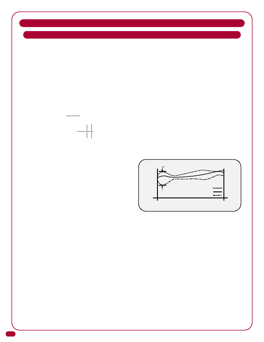
GAIN VARIATION VS. TEMPERATURE
Gain variation versus temperature defines the maxi-
mum allowable variation of the linear gain due to tem-
perature at any discrete frequency. As a result, this
parameter does not account for drift over frequency.
Gain variation versus temperature is measured by
performing swept gain measurements at the specified
temperature extremes and comparing the deviations
between the two sweeps at each frequency to deter-
mine the greatest change. When a ± value is used,
then the delta is taken at both temperature extremes
with respect to room temperature (+23°C).
SPECIFICATION DEFINITIONS (CONT.)
Maximum Variation vs. Temperature
Operating Frequency Range
(Measured at room, hot and cold)
cold
room
Gain
F Low
F High
hot
ρ = Z - Zo
Z + Zo
and:
VSWR =
1 +
ρ
1 -
ρ
相關(guān)PDF資料 |
PDF描述 |
|---|---|
| AM-1571-140 | 100 MHz - 180 MHz RF/MICROWAVE NARROW BAND LOW POWER AMPLIFIER |
| AM-1571-70 | 50 MHz - 90 MHz RF/MICROWAVE NARROW BAND LOW POWER AMPLIFIER |
| AU-2A-1241 | 50 MHz - 90 MHz RF/MICROWAVE NARROW BAND LOW POWER AMPLIFIER |
| AUP-1568 | 5 MHz - 200 MHz RF/MICROWAVE WIDE BAND MEDIUM POWER AMPLIFIER |
| AUIRF1324WL | 240 A, 24 V, 0.0013 ohm, N-CHANNEL, Si, POWER, MOSFET, TO-262AA |
相關(guān)代理商/技術(shù)參數(shù) |
參數(shù)描述 |
|---|---|
| AUPBEZEL4UD | 制造商:Intel 功能描述:BEZEL AUPBEZEL4UD |
| AUPBEZEL4UF | 制造商:Intel 功能描述:RACK BEZEL KIT FOR CONVERTING SERVER CHASSIS P4000 FAMILY PEDESTAL SERVER CHASSIS TO RACK CHASSIS |
| AUPBEZEL4UF 915636 | 制造商:Intel 功能描述:BEZEL AUPBEZEL4UF - Bulk |
| AUPLGPUBR | 制造商:Intel 功能描述: |
| AUPLGPUBR 920612 | 制造商:Intel 功能描述:BRACKET - Boxed Product (Development Kits) |
發(fā)布緊急采購(gòu),3分鐘左右您將得到回復(fù)。