- 您現(xiàn)在的位置:買賣IC網(wǎng) > PDF目錄295120 > AX250-PQ208X79 FPGA, 2816 CLBS, 154000 GATES, 649 MHz, PQFP208 PDF資料下載
參數(shù)資料
| 型號: | AX250-PQ208X79 |
| 元件分類: | FPGA |
| 英文描述: | FPGA, 2816 CLBS, 154000 GATES, 649 MHz, PQFP208 |
| 封裝: | 0.50 MM PITCH, PLASTIC, QFP-208 |
| 文件頁數(shù): | 150/230頁 |
| 文件大小: | 6485K |
| 代理商: | AX250-PQ208X79 |
第1頁第2頁第3頁第4頁第5頁第6頁第7頁第8頁第9頁第10頁第11頁第12頁第13頁第14頁第15頁第16頁第17頁第18頁第19頁第20頁第21頁第22頁第23頁第24頁第25頁第26頁第27頁第28頁第29頁第30頁第31頁第32頁第33頁第34頁第35頁第36頁第37頁第38頁第39頁第40頁第41頁第42頁第43頁第44頁第45頁第46頁第47頁第48頁第49頁第50頁第51頁第52頁第53頁第54頁第55頁第56頁第57頁第58頁第59頁第60頁第61頁第62頁第63頁第64頁第65頁第66頁第67頁第68頁第69頁第70頁第71頁第72頁第73頁第74頁第75頁第76頁第77頁第78頁第79頁第80頁第81頁第82頁第83頁第84頁第85頁第86頁第87頁第88頁第89頁第90頁第91頁第92頁第93頁第94頁第95頁第96頁第97頁第98頁第99頁第100頁第101頁第102頁第103頁第104頁第105頁第106頁第107頁第108頁第109頁第110頁第111頁第112頁第113頁第114頁第115頁第116頁第117頁第118頁第119頁第120頁第121頁第122頁第123頁第124頁第125頁第126頁第127頁第128頁第129頁第130頁第131頁第132頁第133頁第134頁第135頁第136頁第137頁第138頁第139頁第140頁第141頁第142頁第143頁第144頁第145頁第146頁第147頁第148頁第149頁當前第150頁第151頁第152頁第153頁第154頁第155頁第156頁第157頁第158頁第159頁第160頁第161頁第162頁第163頁第164頁第165頁第166頁第167頁第168頁第169頁第170頁第171頁第172頁第173頁第174頁第175頁第176頁第177頁第178頁第179頁第180頁第181頁第182頁第183頁第184頁第185頁第186頁第187頁第188頁第189頁第190頁第191頁第192頁第193頁第194頁第195頁第196頁第197頁第198頁第199頁第200頁第201頁第202頁第203頁第204頁第205頁第206頁第207頁第208頁第209頁第210頁第211頁第212頁第213頁第214頁第215頁第216頁第217頁第218頁第219頁第220頁第221頁第222頁第223頁第224頁第225頁第226頁第227頁第228頁第229頁第230頁

Axcelerator Family FPGAs
2- 12
v2.8
5V Tolerance
There are two schemes to achieve 5V tolerance:
1. 3.3V PCI and 3.3V PCI-X are the only I/O standards
that directly allow 5V tolerance. To implement this,
an internal clamp diode between the input pad and
the VCCI pad is enabled so that the voltage at the
input pin is clamped as shown in EQ 2-3:
Vinput = VCCI + Vdiode = 3.3V + 0.8V = 4.1V
EQ 2-3
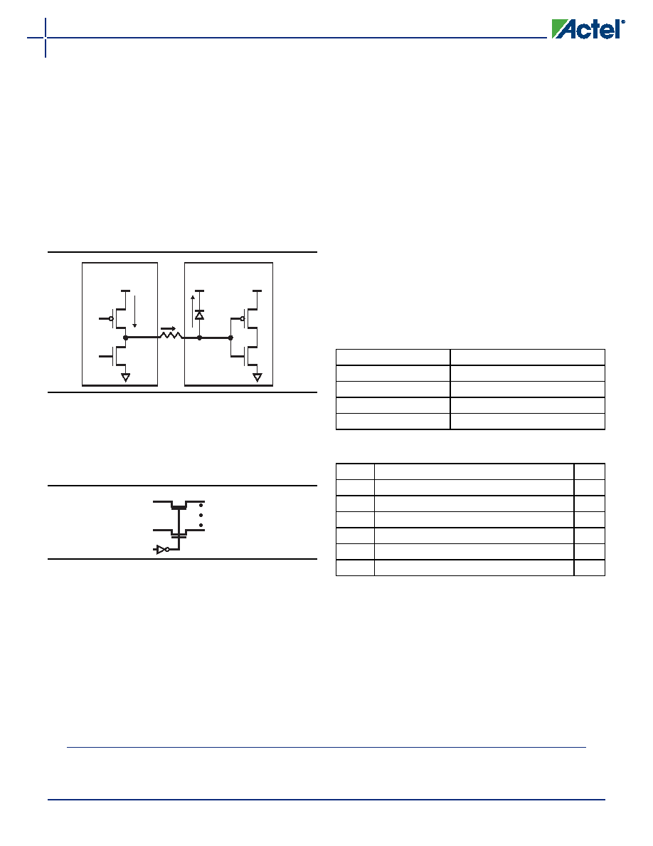
An external series resister (~100
Ω) is required between
the input pin and the 5V signal source to limit the
current (Figure 2-3).
2. 5V tolerance can also be achieved with 3.3V I/O
standards (3.3V PCI, 3.3V PCI-X, and LVTTL) using a
bus-switch product (e.g. IDTQS32X2384). This will
convert the 5V signal to a 3.3V signal with minimum
delay (Figure 2-4).
Simultaneous Switching Outputs (SSO)
When multiple output drivers switch simultaneously,
they induce a voltage drop in the chip/package power
distribution. This simultaneous switching momentarily
raises the ground voltage within the device relative to
the system ground. This apparent shift in the ground
potential to a non-zero value is known as simultaneous
switching noise (SSN) or more commonly, ground
bounce.
SSN becomes more of an issue in high pin count
packages and when using high performance devices such
as the Axcelerator family. Based upon testing, Actel
recommends that users not exceed eight simultaneous
switching outputs (SSO) per each VCCI/GND pair. To ease
this potential burden on designers, Actel has designed all
of the Axcelerator BGAs3 to not exceed this limit with
the exception of the CS180, which has an I/O to VCCI/GND
pair ratio of nine to one.
Please refer to the Simultaneous Switching Noise and
Signal Integrity application note for more information.
I/O Banks and Compatibility
Since each I/O bank has its own user-assigned input
reference voltage (VREF) and an input/output supply
voltage (VCCI), only I/Os with compatible standards can
be assigned to the same bank.
Table 2-11 shows the compatible I/O standards for a
common
VREF
(for
voltage-referenced
standards).
Similarly, Table 2-12 shows compatible standards for a
common VCCI.
summarizes
the
different
combinations of voltages and I/O standards that can be
used together in the same I/O bank. Note that two I/O
standards are compatible if:
Their VCCI values are identical.
Their VREF standards are identical (if applicable).
Figure 2-3 Use of an External Resistor for 5V Tolerance
Figure 2-4 Bus Switch IDTQS32X2384
Non-Actel Part
Actel FPGA
5V
3.3V
PCI
clamp
diode
Rext
5V
3.3V
20X
5V
3. The user should note that in Bank 8 of both AX1000-FG484 and AX500-FG484, there are local violations of this 8:1 ratio.
Table 2-11 Compatible I/O Standards for Different VREF
Values
VREF
Compatible Standards
1.5V
SSTL 3 (Class I and II)
1.25V
SSTL 2 (Class I and II)
1.0V
GTL+ (2.5V and 3.3V Outputs)
0.75V
HSTL (Class I)
Table 2-12 Compatible I/O Standards for Different VCCI
Values
VCCI
1
Compatible Standards
VREF
3.3V
LVTTL, PCI, PCI-X, LVPECL, GTL+ 3.3V
1.0
3.3V
SSTL 3 (Class I and II), LVTTL, PCI, LVPECL
1.5
2.5V
LVCMOS 2.5V, GTL+ 2.5V, LVDS2
1.0
2.5V
LVCMOS 2.5V, SSTL 2 (Classes I and II), LVDS2
1.25
1.8V
LVCMOS 1.8V
N/A
1.5V
LVCMOS 1.5V, HSTL Class I
0.75
Notes:
1. VCCI is used for both inputs and outputs
2. VCCI tolerance is ±5%
相關PDF資料 |
PDF描述 |
|---|---|
| AX250-PQ208 | FPGA, 2816 CLBS, 154000 GATES, 649 MHz, PQFP208 |
| AX250-PQG208I | FPGA, 2816 CLBS, 154000 GATES, 649 MHz, PQFP208 |
| AX250-PQG208M | FPGA, 2816 CLBS, 154000 GATES, 649 MHz, PQFP208 |
| AX250-PQG208 | FPGA, 2816 CLBS, 154000 GATES, 649 MHz, PQFP208 |
| AX250-1FG256I | FPGA, 2816 CLBS, 154000 GATES, 763 MHz, PBGA256 |
相關代理商/技術參數(shù) |
參數(shù)描述 |
|---|---|
| AX250-PQ896 | 制造商:ACTEL 制造商全稱:Actel Corporation 功能描述:Axcelerator Family FPGAs |
| AX250-PQ896B | 制造商:ACTEL 制造商全稱:Actel Corporation 功能描述:Axcelerator Family FPGAs |
| AX250-PQ896I | 制造商:ACTEL 制造商全稱:Actel Corporation 功能描述:Axcelerator Family FPGAs |
| AX250-PQ896M | 制造商:ACTEL 制造商全稱:Actel Corporation 功能描述:Axcelerator Family FPGAs |
| AX250-PQ896PP | 制造商:ACTEL 制造商全稱:Actel Corporation 功能描述:Axcelerator Family FPGAs |
發(fā)布緊急采購,3分鐘左右您將得到回復。