- 您現在的位置:買賣IC網 > PDF目錄166386 > AZ818166 SNAP ACTING/LIMIT SWITCH, SPDT, MOMENTARY, 3A, 24VDC, 6mm, PANEL MOUNT PDF資料下載
參數資料
| 型號: | AZ818166 |
| 元件分類: | 開關 |
| 英文描述: | SNAP ACTING/LIMIT SWITCH, SPDT, MOMENTARY, 3A, 24VDC, 6mm, PANEL MOUNT |
| 文件頁數: | 8/8頁 |
| 文件大小: | 446K |
| 代理商: | AZ818166 |

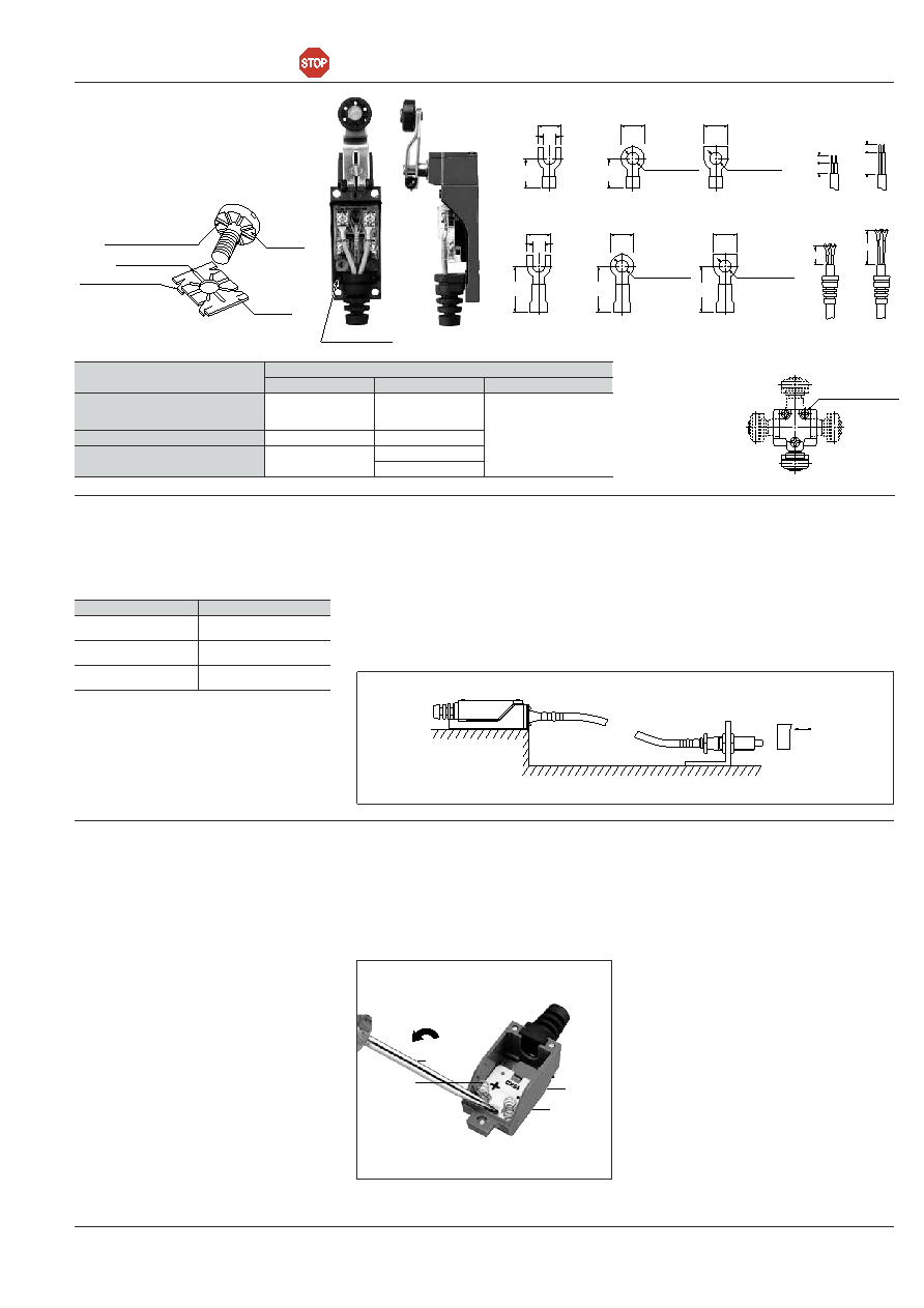
51
CAUTIONS
1. When overtravel is too large, life is short-
ened due to possible damage to the mech-
anism. Please use in the following appropri-
ate range.
2. Because these switches are not of
immersion protected construction, their use
in water or oil should be avoided. Also,
locations where water or oil can normally
impinge upon the switch or where there is
an excessive accumulation of dust should
be avoided.
3. The use of these switches under the fol-
lowing conditions should be avoided. If the
following conditions should become neces-
sary, we recommend consulting us first.
Use where there will be direct contact with
organic solvents, strong acids or alkalis, or
direct exposure to their vapors.
Use where inflammable or corrosive gases
exist.
4. In order to maintain the reliability at a
high level under practical conditions of use,
the actual operating conditions should be
checked for the benefit of the quality of the
product.
WIRING mm inch
-Insulation distance more than 6.4mm
.252inch for wiring and live parts
-Special assembly screws
-Grounding is available
washer
Spring (4 locations)
Projection (8 locations)
Groove (8 points)
screw
Terminal
N.C. use
11
9
N.O. use
27
9
.354
.433
.354
1.063
N.C. use
16
N.O. use
32
.630
1.260
Max. 10
Max. 6.4
3.0 to 3.7 dia.
.394
.118 to .146
Max. 6.4
3.0 to 3.7 dia.
.118 to .146
3.0 to 3.7 dia.
.118 to .146
.252
Max. 10
.394
Max. 14
Max. 6.4
3.0 to 3.7 dia.
.551
.118 to .146
Max. 6.4
Max. 14
.551
Max. 10
.394
3.0 to 3.7 dia.
.118 to .146
Max. 6.4
3.0 to 3.7 dia.
.118 to .146
.252
Applicable fasten terminal
Grounding terminal
With insulated grip
Fasten terminal
Cable treatment
Ordinary terminal
Applicable wire
Head direction change
(Roller arm, adjustable roller arm, adjustable rod types)
Finished outside diameter
Conductor
Wire-strand
Round shape
6 dia. to 9 dia.
Flat shape Max. 9.4
0.75mm21.25mm2
2.0mm2
0.75mm21.25mm2
2-wire
3-wire
4-wire
Wire name
Vinyl cabtire cord (VCTF)
0.75mm2
2-wire
Vinyl cabtire cable (VCT)
1.0 dia. to 1.2 dia.
1.6 dia.
2-wire
600V vinyl insulation sealed cable
(VVF)
Applicable wire
Lock screw (Black)
Actuator heads
may be moved in
90° increments to
any of four direc-
tions, by removing
one screw.
Types
Overtravel
Plunger
(AZ8111, 8112, 8122)
1.5 to 2.0mm
.059 to .079inch
Roller Arm
(AZ8104, 8107, 8108)
20 to 30°
Flexible Rod
(AZ8166, 8169)
15 to 20mm .591 to
.787inch (at the top)
5. Remote wire control types:
Because the main unit is not of water resis-
tant or immersion-proof construction, their
use in water or oil should be avoided. Also,
locations where water or oil can normally
impinge upon the switch or where there is
an excessive accumulation of dust should
be avoided. The main unit should be
installed above the detection part in such
case. (An actuator is immersion-protected
construction.)
6. Mounting
Three cover screws should be fasten uni-
formly. The rubber for opening cord should
be corrected as normal condition after con-
necting the wire.
7. How to change the indicator holder.
1) As shown in the photograph, wrench a
minus-driver in the gap between the cover
and the part of the indicator holder indicat-
ed by the arrow in the direction of insertion,
and raise the lamp a little.
2) After removing the indicator holder,
insert it in the reverse direction, and push it
in until a snap is heard.
3) After changing the direction of the indica-
tor holder, put the cover on it in such a way
that the spring touches the top of the termi-
nal screw.
(Unless the spring rests completely on the
terminal screw, distortion of the spring, fail-
ure in lighting of the lamp or short circuit
may result.)
8. Matters to be attended to in using spring
type VL Limit Switch with indicator.
1) When loads are connected to both N.O.
and N.C. only the indicatin at non-operation
time can be used.
2) Take special care not to damage or
deform the contact spring during change of
indicator holder direction or during connec-
tion work.
3) In the case of VL Limit Switch with Neon
lamp, if the indicator is connected in series
in a 100V circuit, the indicator ceases to be
lighted.
However, for a 200V circuit, up to 2 lamps
can be connected in series.
9. Matters to be attended to in using lead
wire type VL with lamp.
1) When loads are connected to both N.O.
and N.C. indication can be given on both
N.O. and N.C. sides, but it is impossible to
connect the indication circuit to the load in
series.
Detected object
Driver
Lamp
holder
Cover
Spring
VL (AZ8)
Including discontinued products (
)
相關PDF資料 |
PDF描述 |
|---|---|
| AZ810716 | SNAP ACTING/LIMIT SWITCH, SPDT, MOMENTARY, 3A, 24VDC, PANEL MOUNT |
| AZ8107661 | SNAP ACTING/LIMIT SWITCH, SPDT, MOMENTARY, 3A, 24VDC, PANEL MOUNT |
| AZ810766 | SNAP ACTING/LIMIT SWITCH, SPDT, MOMENTARY, 3A, 24VDC, PANEL MOUNT |
| AZ8111161 | SNAP ACTING/LIMIT SWITCH, SPDT, MOMENTARY, 3A, 24VDC, 5.5mm, PANEL MOUNT |
| AZ811116 | SNAP ACTING/LIMIT SWITCH, SPDT, MOMENTARY, 3A, 24VDC, 5.5mm, PANEL MOUNT |
相關代理商/技術參數 |
參數描述 |
|---|---|
| AZ8-1AT-12D | 制造商:American Zettler Inc 功能描述:Electromechanical Relay SPST-NO 10A 12VDC 320Ohm Through Hole |
| AZ8-1AT-12DE | 制造商:American ZETTLER Inc 功能描述: 制造商:American ZETTLER Inc 功能描述:AZ8-1AT-12DE |
| AZ8-1AT-24D | 制造商:American Zettler Inc 功能描述:Electromechanical Relay SPST-NO 10A 24VDC 1.28KOhm Through Hole |
| AZ8-1AT-24DE | 制造商:American Zettler Inc 功能描述:Electromechanical Relay SPST-NO 10A 24VDC 1.28KOhm Through Hole |
| AZ8-1AT-24DEF | 制造商:American Zettler Inc 功能描述:AZ8 Series 10 A SPST 24 VDC PCB Mount Heavy Duty Sealed Miniature Power Relay |
發(fā)布緊急采購,3分鐘左右您將得到回復。