- 您現(xiàn)在的位置:買賣IC網(wǎng) > PDF目錄166386 > AZD1009F SNAP ACTING/LIMIT SWITCH, SPST, MOMENTARY, 5A, 24VDC, 9mm, PANEL MOUNT PDF資料下載
參數(shù)資料
| 型號: | AZD1009F |
| 元件分類: | 開關 |
| 英文描述: | SNAP ACTING/LIMIT SWITCH, SPST, MOMENTARY, 5A, 24VDC, 9mm, PANEL MOUNT |
| 封裝: | CADMIUM FREE |
| 文件頁數(shù): | 21/23頁 |
| 文件大?。?/td> | 698K |
| 代理商: | AZD1009F |

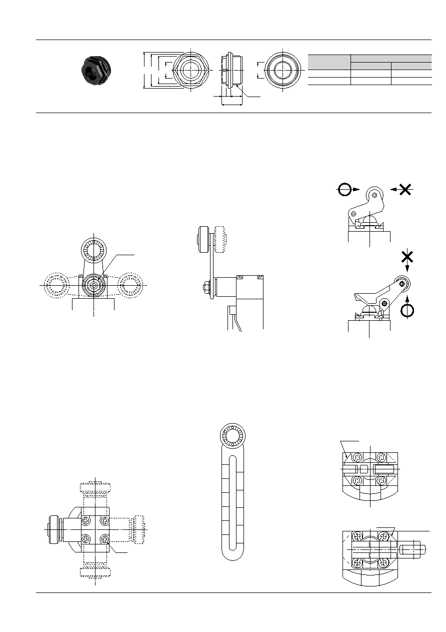
49
Arm Setting Position
The roller arm of the arm types
(AZD1003, AZD1004, AZD1008,
AZD1053, AZD1054 and AZD1058) can
be set in any position at 15° intervals.
Loosen the arm fastening hex. nut, repo-
sition the arm, and retighten the hex. nut.
When doing so tighten the hex. nut with
the arm secured to the unit. Tightening
without securing may cause damage.
Also, the same is true of the adjustable
rod types (AZD1007 and AZD1057).
Roller Direction
The roller of the arm types (AZD1003,
AZD1004, AZD1008, AZD1053,
AZD1054 and AZD1058) can be mount-
ed on the front and rear (dotted line in
the figure) sides of the switch, as shown
below. (Positioned on the front side at
delivery.)
To set the roller on the rear side, remove
the arm fastening hex. nut, and reinsert
the arm so as to face the roller in the
rear direction. Then, retighten the hex.
nut.
Roller Lever Direction
AZD1000, AZD1009, AZD1050 and
AZD1059 type is move a detection object
in the D direction as shown below. Be
sure not to move the object oppositely.
If the opposite direction is required,
change the direction of the lever.
Hex. nut
Adjustable Arm Length
To adjust the length of the adjustable
arm of AZD1003, AZD1008, AZD1053
and AZD1058, slightly loosen the arm
fastening hex. nut, and adjust the length.
The adjustable arm is graduated in two
kinds of length units. Use these indica-
tions as the reference during adjustment.
20
40
60
3
2
1
D
The roller lever can be set in two direc-
tions at 180° intervals. (Even though it
can be also set in the 90° direction, the
mounting surface will project.) Remove
the four lever base fastening screws,
turn the lever together with the lever
base in 180°, and retighten the four
screws at a torque of 0.20 to 0.39 Nm {2
to 4 kgcm}.
Mounting surface
Lever base
Mounting
surface
Lever base
Head Block Direction
The head of the arm types (AZD1003,
AZD1004, AZD1008, AZD1053,
AZD1054 and AZD1058) can be set in
any of four directions at 90° intervals, but
not in any other intermediate directions.
Loosen four screws on the upper side of
the head, and set the head in a desired
direction, and retighten them at a torque
of 0.20 to 0.39 Nm {2 to 4 kgcm}. Be
careful not to use too much strength
when tightening as this will cause the
threads to strip. Also, the same is true of
the adjustable rod types (AZD1007 and
AZD1057).
Screw
DL (AZD1)
Conduit connector
AZD1830
General tolerance: ±0.5 ±.020
11 dia.
25 dia. 22
19
(14)
33
G.1/2
8
11 dia.
(.551)
.118
.118 .315
.433
.984
.748
.866
Rubber seal
inside diameter
9 dia. (.354)
Adaptable cable outer diameter
Min.
Max.
7.5 dia. (.295)
9.5 dia. (.374)
11 dia. (.433)
9 dia. (.354)
11 dia. (.433)
mm inch
相關PDF資料 |
PDF描述 |
|---|---|
| AZD1002 | SNAP ACTING/LIMIT SWITCH, SPST, MOMENTARY, 5A, 24VDC, 6mm, PANEL MOUNT |
| AZD1053F | SNAP ACTING/LIMIT SWITCH, SPST, MOMENTARY, 5A, 24VDC, PANEL MOUNT |
| AZH1224 | SNAP ACTING/LIMIT SWITCH, SPDT, MOMENTARY, 11mm, PANEL MOUNT |
| AZH1002 | SNAP ACTING/LIMIT SWITCH, SPDT, MOMENTARY, 5A, 30VDC, 4.5mm, PANEL MOUNT |
| AZH1011 | SNAP ACTING/LIMIT SWITCH, SPDT, MOMENTARY, 5A, 30VDC, 4.5mm, PANEL MOUNT |
相關代理商/技術參數(shù) |
參數(shù)描述 |
|---|---|
| AZD1050 | 制造商:Panasonic Electric Works 功能描述: |
| AZD1050CEJ | 制造商:Panasonic Electric Works 功能描述:Limit switch one-way roll positive open |
| AZD1051CEJ | 制造商:Panasonic Electric Works 功能描述:limit switch, push plunger |
| AZD1052 | 制造商:Panasonic Electric Works 功能描述:Switch Limit N.O./N.C. SPDT Top Roller Plunger Conduit 6A 380VAC 220VDC 6.37N Linear Screw Mount |
| AZD1052CEJ | 制造商:Panasonic Electric Works 功能描述:limit switch, roller plunger |
發(fā)布緊急采購,3分鐘左右您將得到回復。