- 您現(xiàn)在的位置:買賣IC網(wǎng) > PDF目錄369473 > BLV97 (NXP SEMICONDUCTORS) RM Series - Econoline Unregulated DC-DC Converters; Input Voltage (Vdc): 3.3V; Output Voltage (Vdc): 3.3V; Power: 0.25W; Single Output Rail; Industry Standard Pinout; 1kVDC & 2kVDC Isolation; High Efficiency for Low Power Applications; UL94V-0 Package Material; Optional Continuous Short Circuit Protected; Fully Encapsulated; Efficiency to 80%; Custom versions available PDF資料下載
參數(shù)資料
| 型號: | BLV97 |
| 廠商: | NXP SEMICONDUCTORS |
| 元件分類: | 功率晶體管 |
| 英文描述: | RM Series - Econoline Unregulated DC-DC Converters; Input Voltage (Vdc): 3.3V; Output Voltage (Vdc): 3.3V; Power: 0.25W; Single Output Rail; Industry Standard Pinout; 1kVDC & 2kVDC Isolation; High Efficiency for Low Power Applications; UL94V-0 Package Material; Optional Continuous Short Circuit Protected; Fully Encapsulated; Efficiency to 80%; Custom versions available |
| 中文描述: | UHF BAND, Si, NPN, RF POWER TRANSISTOR |
| 文件頁數(shù): | 3/11頁 |
| 文件大小: | 65K |
| 代理商: | BLV97 |
March 1993
3
Philips Semiconductors
Product specification
UHF power transistor
BLV97CE
LIMITING VALUES
Limiting values in accordance with the Absolute Maximum System (IEC 134)
THERMAL RESISTANCE
SYMBOL
PARAMETER
CONDITIONS
MIN.
MAX.
UNIT
V
CBO
V
CEO
V
EBO
I
C
I
CM
collector base voltage
collector emitter voltage
emitter base voltage
collector current
collector current
open emitter
open base
open collector
DC or average
peak value
f
>
1 MHz
f
>
1 MHz
T
mb
= 25
°
C
50
27
3.5
3
9
V
V
V
A
A
P
tot
total power dissipation
70
W
T
stg
T
j
storage temperature
operating junction temperature
65
150
200
°
C
°
C
SYMBOL
PARAMETER
CONDITIONS
TYP.
MAX.
UNIT
R
thj-mb
R
th mb-h
from junction to mounting base (RF)
from mounting base to heatsink
2.3
0.4
K/W
K/W
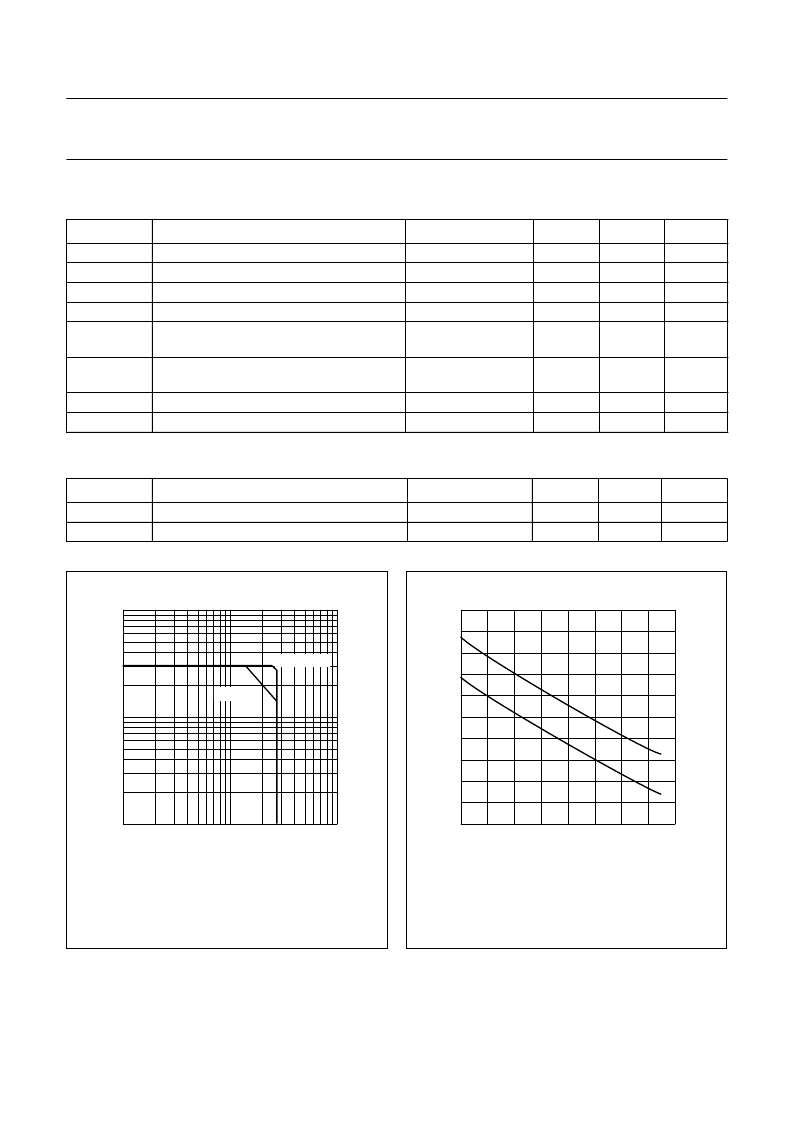
Fig.2 DC SOAR.
handbook, halfpage
1
10
1
MDA441
1
10
VCE (V)
IC
(A)
10
2
Th = 70
°
C
Tmb = 25
°
C
Fig.3
Power/temperature derating;
I: DC or RF operation;
II: short-term operation during mismatch.
handbook, halfpage
(W)
0
II
I
40
80
Th (
°
C)
160
0
80
120
60
40
20
MDA442
相關(guān)PDF資料 |
PDF描述 |
|---|---|
| BLW29 | VHF power transistor |
| BLW30 | VHF power transistor |
| BLW32 | UHF linear power transistor(UHF線性功率晶體管) |
| BLW33 | UHF Linear power transistor(UHF 線性功率晶體管) |
| BLW34 | UHF Linear power transistor(UHF 線性功率晶體管) |
相關(guān)代理商/技術(shù)參數(shù) |
參數(shù)描述 |
|---|---|
| BLV97CE | 制造商:PHILIPS 制造商全稱:NXP Semiconductors 功能描述:UHF power transistor |
| BLV98CE | 制造商:PHILIPS 制造商全稱:NXP Semiconductors 功能描述:UHF power transistor |
| BLV99 | 制造商:ASI 制造商全稱:ASI 功能描述:NPN SILICON RF POWER TRANSISTOR |
| BLV99/SL | 制造商:未知廠家 制造商全稱:未知廠家 功能描述:RF Power Transistors for UHF |
| BLV99SL | 功能描述:射頻雙極電源晶體管 RF Bipolar Trans RoHS:否 制造商:M/A-COM Technology Solutions 配置:Single 直流集電極/Base Gain hfe Min:40 最大工作頻率:30 MHz 集電極—發(fā)射極最大電壓 VCEO:25 V 發(fā)射極 - 基極電壓 VEBO:4 V 集電極連續(xù)電流:20 A 最大直流電集電極電流: 功率耗散:250 W 封裝 / 箱體:Case 211-11 封裝:Tray |
發(fā)布緊急采購,3分鐘左右您將得到回復(fù)。