- 您現在的位置:買賣IC網 > PDF目錄166502 > BU-61582F2-451S (DATA DEVICE CORP) 2 CHANNEL(S), 1M bps, MIL-STD-1553 CONTROLLER, CDFP70 PDF資料下載
參數資料
| 型號: | BU-61582F2-451S |
| 廠商: | DATA DEVICE CORP |
| 元件分類: | 微控制器/微處理器 |
| 英文描述: | 2 CHANNEL(S), 1M bps, MIL-STD-1553 CONTROLLER, CDFP70 |
| 封裝: | CERAMIC, DFP-70 |
| 文件頁數: | 7/48頁 |
| 文件大?。?/td> | 378K |
| 代理商: | BU-61582F2-451S |
第1頁第2頁第3頁第4頁第5頁第6頁當前第7頁第8頁第9頁第10頁第11頁第12頁第13頁第14頁第15頁第16頁第17頁第18頁第19頁第20頁第21頁第22頁第23頁第24頁第25頁第26頁第27頁第28頁第29頁第30頁第31頁第32頁第33頁第34頁第35頁第36頁第37頁第38頁第39頁第40頁第41頁第42頁第43頁第44頁第45頁第46頁第47頁第48頁

15
Data Device Corporation
www.ddc-web.com
BU-61582
G-08/02-250
BC MESSAGE BLOCK FORMATS AND BC CONTROL
WORD
In BC mode, the BU-61582 supports all MIL-STD-1553 message
formats. For each 1553 message format, the BU-61582 man-
dates a specific sequence of words within the BC Message
Block. This includes locations for the Control, Command and
(transmitted) Data Words that are to be read from RAM by the
BC-to-RT Transfer
Control Word
Receive Command Word
Data Word #1
Data Word #2
.
Last Data Word
Last Data Word Looped Back
Status Received
Last Data Word
.
Data Word #2
Data Word #1
Status Received
Transmit Command Looped Back
Transmit Command Word
Control Word
RT-to-BC Transfer
Transmit Command
Looped Back
Rx RT Status Word
Last Data
.
Data #2
Data #1
Tx RT Status Word
Transmit Command
Receive Command
Control Word
RT-to-RT Transfer
Mode Command
Looped Back
Status Received
Mode Command
Control Word
Mode Code;
No Data
Mode Command
Looped Back
Data Word
Status Received
Tx Mode Command
Control Word
Tx Mode Code;
With Data
Tx Command
Looped Back
Last Data
.
Data #2
Data #1
Tx RT Status Word
Tx Command
Rx Broadcast Command
Control Word
RT-to-RTs (Broadcast)
Transfer
Last Data Status
Word
Last Data
.
Data #2
Data #1
Broadcast Command
Control Word
Broadcast
Data Word
Data Word Looped
Back
Status Received
Rx Mode Command
Control Word
Rx Mode Code;
With Data
Broadcast Mode Command
Looped Back
Broadcast Mode Command
Control Word
Broadcast Mode Code;
No Data
Data Word Looped Back
Data Word
Broadcast Mode Command
Control Word
Broadcast Mode Code;
With Data
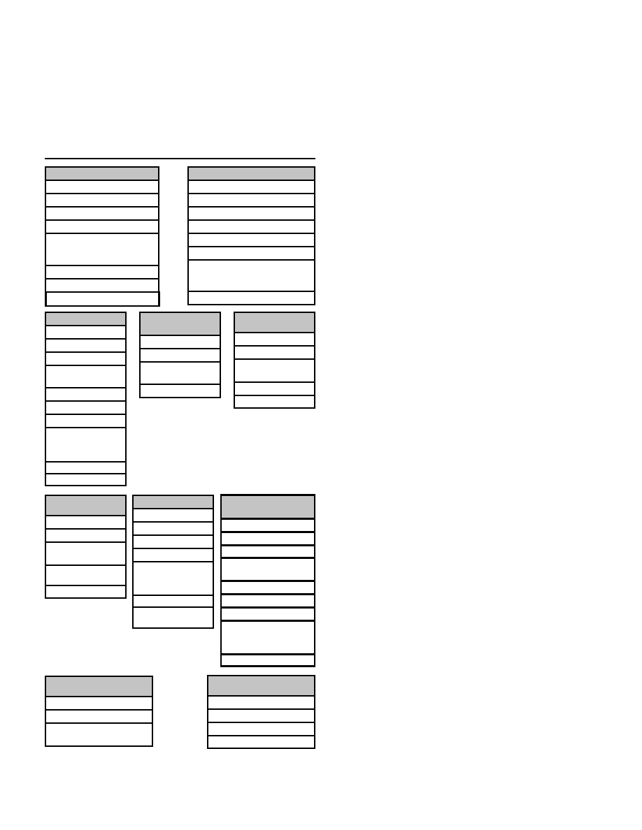
FIGURE 4. BC MESSAGE BLOCK FORMATS
BC protocol logic. In addition, subsequent contiguous locations
must be allocated for storage of received Loopback, RT Status
and Data Words. FIGURE 4 illustrates the organization of the BC
message blocks for the various MIL-STD-1553 message for-
mats. Note that for all of the message formats, the BC Control
Word is located in the first location of the message block.
The BC Control Word is not transmitted on the 1553 bus.
Instead, it contains bits that select the active bus and message
format, enable off-line self-test, masking of Status Word bits,
enable retries and interrupts, and specify MIL-STD-1553A or -
1553B error handling. The bit mapping and definitions of the BC
Control Word are illustrated in TABLE 10.
The BC Control Word is followed by the Command Word to be
transmitted, and subsequently by a second Command Word (for
an RT-to-RT transfer), followed by Data Words to be transmitted
(for Receive commands). The location after the last word to be
transmitted is reserved for the Loopback Word. The loopback
Word is an on-line self-test feature. The subsequent locations
after the Loopback Word are reserved for received Status Words
and Data Words (for Transmit commands).
AUTOMATIC RETRIES
The BU-61582 BC implements automatic message retries. When
enabled, retries will occur, following response timeout or format
error conditions. As additional options, retries may be enabled
when the Message Error Status Word bit is set by a 1553A RT or
following a “Status Set” condition. For a failed message, either
one or two message retries will occur, the bus channel (same or
alternate) is independently programmable for the first and sec-
ond retry attempts. Retries may be enabled or disabled on an
individual message basis.
BC INTERRUPTS
BC interrupts may be enabled by the Interrupt Mask Register for
Stack Rollover, Retry, End-of-Message (global), End-of-
Message (in conjunction with the BC Control Word for individual
messages), response timeout, message error, end of BC frame,
and Status Set conditions. The definition of “Status Set” is pro-
grammable on an individual message basis by means of the BC
Control Word. This allows for masking (“care/don’t care”) for the
individual RT Status Word bits.
REMOTE TERMINAL (RT) ARCHITECTURE
The RT protocol design of the BU-61582 represents DDC’s fifth
generation implementation of a 1553 RT. One of the salient fea-
tures of the SP’ACE’s RT architecture is its true multiprotocol
functionality. This includes programmable options for support of
MIL-STD-1553A, the various McAir protocols, and MIL-STD-
1553B Notice 2. The BU-61582 RT response time is 2 to 5 s
dead time (4 to 7 s per 1553B), providing compliance to all the
1553 protocols. Additional multiprotocol features of the BU-
61582 include options for full software control of RT Status and
Built-in-Test (BIT) words. Alternatively, for 1553B applications,
相關PDF資料 |
PDF描述 |
|---|---|
| BU-61582F2-460Z | 2 CHANNEL(S), 1M bps, MIL-STD-1553 CONTROLLER, CDFP70 |
| BU-61582F2-461W | 2 CHANNEL(S), 1M bps, MIL-STD-1553 CONTROLLER, CDFP70 |
| BU-61582F2-471L | 2 CHANNEL(S), 1M bps, MIL-STD-1553 CONTROLLER, CDFP70 |
| BU-61582F2-471Y | 2 CHANNEL(S), 1M bps, MIL-STD-1553 CONTROLLER, CDFP70 |
| BU-61582F2-480W | 2 CHANNEL(S), 1M bps, MIL-STD-1553 CONTROLLER, CDFP70 |
相關代理商/技術參數 |
參數描述 |
|---|---|
| BU-61585 | 制造商:未知廠家 制造商全稱:未知廠家 功能描述:MIL-STD-1553 Components |ACE |
| BU-61586 | 制造商:未知廠家 制造商全稱:未知廠家 功能描述:MIL-STD-1553 Components |ACE |
| BU61586V6-300 | 制造商:DDC 功能描述:MIL-STD-1553/ARINC BUS CONTROLLER/RTU, 70 Pin, Flat Pack |
| BU-61588 | 制造商:未知廠家 制造商全稱:未知廠家 功能描述:MINIATURE ADVANCED COMMUNICATION ENGINE (MINI-ACE) AND MINI-ACE PLUS |
| BU-61588F0 | 制造商:未知廠家 制造商全稱:未知廠家 功能描述:MINIATURE ADVANCED COMMUNICATION ENGINE (MINI-ACE) AND MINI-ACE PLUS |
發(fā)布緊急采購,3分鐘左右您將得到回復。