- 您現(xiàn)在的位置:買賣IC網(wǎng) > PDF目錄257698 > CS1601-7PD4 1-OUTPUT 100 W DC-DC REG PWR SUPPLY MODULE PDF資料下載
參數(shù)資料
| 型號: | CS1601-7PD4 |
| 元件分類: | 電源模塊 |
| 英文描述: | 1-OUTPUT 100 W DC-DC REG PWR SUPPLY MODULE |
| 封裝: | HEAT SINK, METAL, CASE S02, MODULE |
| 文件頁數(shù): | 18/31頁 |
| 文件大小: | 633K |
| 代理商: | CS1601-7PD4 |
第1頁第2頁第3頁第4頁第5頁第6頁第7頁第8頁第9頁第10頁第11頁第12頁第13頁第14頁第15頁第16頁第17頁當(dāng)前第18頁第19頁第20頁第21頁第22頁第23頁第24頁第25頁第26頁第27頁第28頁第29頁第30頁第31頁

Cassette Style
100 Watt DC-DC Converters
S Series
Edition 1/01.2000
25/31
-9 Extended Temperature Range
Option -9 extends the operational ambient temperature
range from –25...71
°C (standard) to –40...71°C. The
power supplies provide full nominal output power with con-
vection cooling. Option -9 excludes inrush current limitation
by NTC.
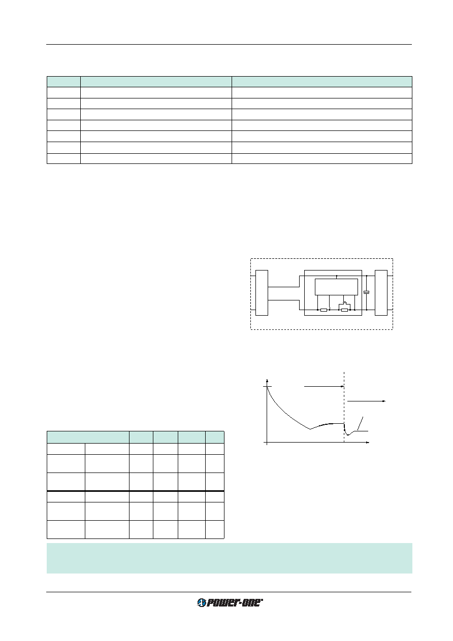
E Inrush Current Limitation
CS/DS/ES types may be supplemented by an electronic
circuit (option E, replacing the standard built-in NTC) to
achieve an enhanced inrush current limiting function (not
available with AS and BS types).
If fitted with option E (inrush current limitation) together with
option D6, input voltage monitoring, the CS units meet the
CEPT/ETSI standards for 48 V DC supply voltages accord-
ing to prETS 300132-2, version 4.2, date 9312. Option D6,
externally adjustable via potentiometer, is necessary to dis-
able the converter at input voltages below actual service
voltage ranges, avoiding an excessive input current when
the
input
voltage
is
raised
slowly
according
to
prETS 300132-2. Option D6 threshold level should be ad-
justed to 36.0...40.5 V for 48 V nominal supply systems or
44.0...50.0 V for 60 V nominal supply systems (refer also to
description of option D). The D output should be connected
to the inhibit input. Please contact Power-One if applica-
tions do not permit potentiometer setting.
RV: Current limiting resistance = RS + RI = 15
[A]
Ui/RV
<30
t [ms]
CapacitorCi
fully charged
Normal operation
(current limiting
circuit is fully
conducting)
0
Ii = Pi/Ui
11039
Fig. 26
Inrush current with option E
Table 16: Inrush current characteristics with option E
Characteristics
CS
DS
ES
Unit
Ui nom, Io nom Input voltage
60
110
220
V
Iinr p
Peak inrush
6.8
7.4
14.6
A
current
tinr
Inrush current
18
14
16
ms
duration
Ui max, Io nom Input voltage
140
220
380
V
Iinr p
Peak inrush
9.3
14.5
25.3
A
current
tinr
Inrush current
20
14
12
ms
duration
Precaution:
Subsequent switch-on cycles at start-up are limited to max. 10 cycles during the first 20 seconds (cold unit) and at con-
tinuing on/off (
TC =95°C) max. 1 cycle every 8 sec.
Input
Filter
Control
Converter
FET
Ci
RI
RS
10017
Fig. 25
Option E block diagram
Description of Options
Table 15: Survey of options
Option
Function of option
Characteristic
–9
Extended operational ambient temperature range
TA = –40...71°C
E
Electronic inrush current limitation circuitry
Active inrush current limitation for CS, DS, ES, FS
P 1
Potentiometer for fine adjustment of output voltage
Adjustment range +10/-60% of
Uo nom, excludes R input
D 2
Input and/or output undervoltage monitoring circuitry
Safe data signal output (D0...DD)
V 2 3
Input and/or output undervoltage monitoring circuitry
ACFAIL signal according to VME specifications (V0, V2, V3)
T
Current sharing
Interconnect T-pins if paralleling outputs (5 units max.)
B1/B2
Cooling plate
Replaces standard heat sink, allowing direct chassis-mounting
1 Function R excludes option P and vice versa
2 Option D excludes option V and vice versa
3 Only available if main output voltage Uo1 = 5.1 V
相關(guān)PDF資料 |
PDF描述 |
|---|---|
| CS1601-7RD9 | 1-OUTPUT 100 W DC-DC REG PWR SUPPLY MODULE |
| CS1601-9EPD5B2 | 1-OUTPUT 100 W DC-DC REG PWR SUPPLY MODULE |
| CS1601-9EPD9TB2 | 1-OUTPUT 100 W DC-DC REG PWR SUPPLY MODULE |
| CS1601-9ERD0T | 1-OUTPUT 100 W DC-DC REG PWR SUPPLY MODULE |
| CS1601-9PD2B1 | 1-OUTPUT 100 W DC-DC REG PWR SUPPLY MODULE |
相關(guān)代理商/技術(shù)參數(shù) |
參數(shù)描述 |
|---|---|
| CS1601-7R | 功能描述:EURO-CASSETTE 100W 24V RoHS:否 類別:電源 - 外部/內(nèi)部(非板載) >> DC DC Converters 系列:* 標(biāo)準(zhǔn)包裝:1 系列:Quint 類型:隔離 輸入電壓:24V 輸出:24V 輸出數(shù):1 輸出 - 1 @ 電流(最大):24 VDC @ 50A 輸出 - 2 @ 電流(最大):- 輸出 - 3 @ 電流(最大):- 輸出 - 4 @ 電流(最大):- 功率(瓦特):1200W 安裝類型:底座安裝 工作溫度:0°C ~ 40°C 效率:- 封裝/外殼:模塊 尺寸/尺寸:4.33" L x 9.09" W x 6.14" H(110mm x 231mm x 156mm) 包裝:散裝 電源(瓦特)- 最大:1200W 批準(zhǔn):- 其它名稱:277-69722866365-NDQUINT-BAT/24DC/12AH |
| CS1601-9ER | 制造商:Power-One 功能描述:DCDC - Bulk |
| CS1601AM | 制造商:Rochester Electronics LLC 功能描述:- Bulk |
| CS1601-FSZ | 功能描述:功率因數(shù)校正 IC PFC CONTROLLER DCM RoHS:否 制造商:Fairchild Semiconductor 開關(guān)頻率:300 KHz 最大功率耗散: 最大工作溫度:+ 125 C 安裝風(fēng)格:SMD/SMT 封裝 / 箱體:SOIC-8 封裝:Reel |
| CS1601-FSZR | 制造商:Cirrus Logic 功能描述:IC PFC CONTROLLER DCM OCP (FOR LIGHTING) - Tape and Reel 制造商:Cirrus Logic 功能描述:IC PFC CTRLR BALLAST 8SOIC 制造商:Cirrus Logic 功能描述:PFC Controller |
發(fā)布緊急采購,3分鐘左右您將得到回復(fù)。