- 您現(xiàn)在的位置:買賣IC網(wǎng) > PDF目錄257698 > CS1601-9PD2B1 1-OUTPUT 100 W DC-DC REG PWR SUPPLY MODULE PDF資料下載
參數(shù)資料
| 型號(hào): | CS1601-9PD2B1 |
| 元件分類: | 電源模塊 |
| 英文描述: | 1-OUTPUT 100 W DC-DC REG PWR SUPPLY MODULE |
| 封裝: | METAL, CASE S02, MODULE |
| 文件頁(yè)數(shù): | 28/31頁(yè) |
| 文件大小: | 633K |
| 代理商: | CS1601-9PD2B1 |
第1頁(yè)第2頁(yè)第3頁(yè)第4頁(yè)第5頁(yè)第6頁(yè)第7頁(yè)第8頁(yè)第9頁(yè)第10頁(yè)第11頁(yè)第12頁(yè)第13頁(yè)第14頁(yè)第15頁(yè)第16頁(yè)第17頁(yè)第18頁(yè)第19頁(yè)第20頁(yè)第21頁(yè)第22頁(yè)第23頁(yè)第24頁(yè)第25頁(yè)第26頁(yè)第27頁(yè)當(dāng)前第28頁(yè)第29頁(yè)第30頁(yè)第31頁(yè)

Cassette Style
100 Watt DC-DC Converters
S Series
Edition 1/01.2000
6/31
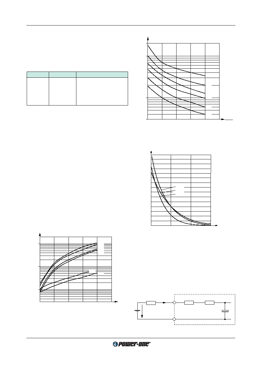
Static Input Current Characteristic
2
345
6
1
1.00
10.00
FS
CS
ES
Ui
Ui min
Ii (A)
DS
20.00
AS
BS
04037
Input Inrush Current Characteristic
1
23
t [ms]
0
50
100
Ii inr [A]
150
CS
ES
DS
04038
Fig. 4
Typical inrush current versus time at Ui max, Rext = 0.
For AS, BS and FS as well as for application related val-
ues use the formula given in Inrush Current Peak Value to
get realistic results.
Fig. 3
Typical input current versus relative input voltage.
Input Fuse
A fuse mounted inside the converter protects the module
against severe defects. This fuse may not fully protect the
module when the input voltage exceeds 200 V DC! In appli-
cations where the converters operate at source voltages
above 200 V DC an external fuse or a circuit breaker at sys-
tem level should be installed!
Table 3: Fuse Specification
Module
Fuse type
Fuse rating
AS 1
fast-blow
Little fuse 314
30.0 A, 125 V
BS 1
fast-blow
Little fuse 314
25.0 A, 125 V
CS 2
slow-blow
SPT
12.5 A, 250 V
DS 2
slow-blow
SPT
8 A, 250 V
ES 2
slow-blow
SPT
4 A, 250 V
FS 2
slow-blow
SPT
16 A, 250 V
1 Fuse size 6.3
× 32 mm
2 Fuse size 5
× 20 mm
Reverse Polarity
The units are not protected against reverse polarity at the
input to avoid unwanted power losses and may be dam-
aged.
Input Transient Protection
A suppressor diode or a VDR (depending upon the input
voltage range) together with the input fuse and a symmetri-
cal input filter form an effective protection against high input
transient voltages which typically occur in most installa-
tions, but especially in battery driven mobile applications.
Nominal battery voltages in use are: 12, 24, 36, 48, 60, 72,
110 and 220 V. In most cases each nominal value is speci-
fied in a tolerance of –30...+25%.
In certain applications, surges according to RIA 12 are
specified in addition to those defined in IEC 571-1. The
power supply must not switch off during these surges and
since their energy can practically not be absorbed an ex-
tremely wide input range is required. The ES input range for
110 V batteries has been designed and tested to meet this
requirement.
Fig. 5
Typical hold-up time th versus relative input voltage Ui/Ui min.
The DC-DC converters require an external series diode in
the input path if other loads are connected to the same in-
put supply lines.
2
345
6
1
0.30
1.00
U i
–––––
Ui min
t h (ms)
10.00
100.00
DS
CS
ES
FS
AS
BS
04041
Hold-up Time versus relative Input Voltage
Rs ext
Ri
RNTC
Iinr p
Ui source
+
Ci int
04040
Fig. 6
Equivalent circuit for input impedance
Inrush Current Peak Value
The inrush current peak value (initial switch-on cycle) can
be determined by following calculation: (see also
Input In-
rush Current Characteristics)
Ui source
Iinr p = ––––––––––––––––
(
Rs ext + Ri + RNTC)
相關(guān)PDF資料 |
PDF描述 |
|---|---|
| CS1601-9PD2B2 | 1-OUTPUT 100 W DC-DC REG PWR SUPPLY MODULE |
| CS1601-9PD3 | 1-OUTPUT 100 W DC-DC REG PWR SUPPLY MODULE |
| CS1601-9PD4B2 | 1-OUTPUT 100 W DC-DC REG PWR SUPPLY MODULE |
| CS2320-7ERD5 | 2-OUTPUT 100 W DC-DC REG PWR SUPPLY MODULE |
| CS2320-7PD4T | 2-OUTPUT 100 W DC-DC REG PWR SUPPLY MODULE |
相關(guān)代理商/技術(shù)參數(shù) |
參數(shù)描述 |
|---|---|
| CS1601AM | 制造商:Rochester Electronics LLC 功能描述:- Bulk |
| CS1601-FSZ | 功能描述:功率因數(shù)校正 IC PFC CONTROLLER DCM RoHS:否 制造商:Fairchild Semiconductor 開關(guān)頻率:300 KHz 最大功率耗散: 最大工作溫度:+ 125 C 安裝風(fēng)格:SMD/SMT 封裝 / 箱體:SOIC-8 封裝:Reel |
| CS1601-FSZR | 制造商:Cirrus Logic 功能描述:IC PFC CONTROLLER DCM OCP (FOR LIGHTING) - Tape and Reel 制造商:Cirrus Logic 功能描述:IC PFC CTRLR BALLAST 8SOIC 制造商:Cirrus Logic 功能描述:PFC Controller |
| CS1601H | 制造商:CIRRUS 制造商全稱:Cirrus Logic 功能描述:Digital PFC Controller for Electronic Ballasts |
| CS1601H-FSZ | 制造商:Cirrus Logic 功能描述:IC PFC CONTROLLER DCM OCP (100KHZ) - Bulk 制造商:Cirrus Logic 功能描述:IC PFC CTRLR BALLAST 8SOIC 制造商:Cirrus Logic 功能描述:PFC Controller |
發(fā)布緊急采購(gòu),3分鐘左右您將得到回復(fù)。