- 您現(xiàn)在的位置:買(mǎi)賣(mài)IC網(wǎng) > PDF目錄170246 > CW025AJ-M (LINEAGE POWER LLC) 2-OUTPUT 13.125 W DC-DC REG PWR SUPPLY MODULE PDF資料下載
參數(shù)資料
| 型號(hào): | CW025AJ-M |
| 廠(chǎng)商: | LINEAGE POWER LLC |
| 元件分類(lèi): | 電源模塊 |
| 英文描述: | 2-OUTPUT 13.125 W DC-DC REG PWR SUPPLY MODULE |
| 封裝: | MODULE-7 |
| 文件頁(yè)數(shù): | 16/16頁(yè) |
| 文件大?。?/td> | 559K |
| 代理商: | CW025AJ-M |
第1頁(yè)第2頁(yè)第3頁(yè)第4頁(yè)第5頁(yè)第6頁(yè)第7頁(yè)第8頁(yè)第9頁(yè)第10頁(yè)第11頁(yè)第12頁(yè)第13頁(yè)第14頁(yè)第15頁(yè)當(dāng)前第16頁(yè)
Lineage Power
9
Data Sheet
April 2008
36 Vdc to 75 Vdc Input; 25 W
CW025 Dual Output-Series Power Modules:
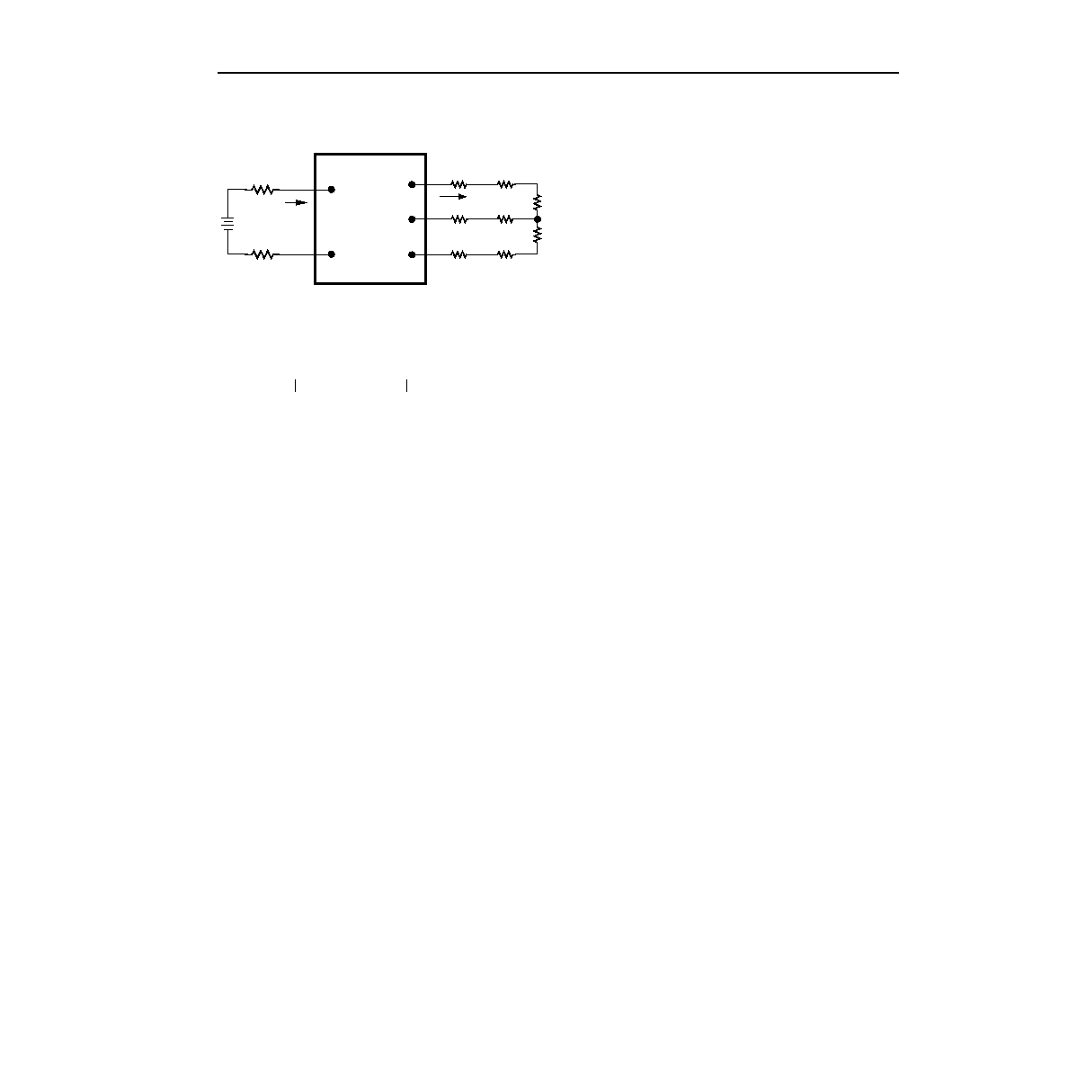
Test Congurations (continued)
8-863(C).a
Note: All measurements are taken at the module terminals. When
socketing, place Kelvin connections at module terminals to
avoid measurement errors due to socket contact resistance.
Figure 13. Output Voltage and Efciency Measure-
ment Test Setup
Design Considerations
Grounding Considerations
For modules without the isolated case ground pin
option, the case is internally connected to the VI(+) pin.
Input Source Impedance
The power module should be connected to a low ac-
impedance input source. Highly inductive source
impedances can affect the stability of the power mod-
ule. A 33 F electrolytic capacitor (ESR < 0.7
at
100 kHz) mounted close to the power module helps
ensure stability of the unit.
Note: VI(+) is internally connected to the case for a
standard module.
Safety Considerations
For safety agency approval of the system in which the
power module is used, the power module must be
installed in compliance with the spacing and separation
requirements of the end-use safety agency standard,
i.e.,
UL-1950, CSA 22.2-950, EN60950.
For the converter output to be considered meeting the
requirements of safety extra-low voltage (SELV), one of
the following must be true of the dc input:
s
All inputs are SELV and oating with the output also
oating.
s
All inputs are SELV and grounded with the output
also grounded.
s
Any non-SELV input must be provided with rein-
forced insulation from any other hazardous voltages,
including the ac mains, and must have an SELV reli-
ability test performed on it in combination with the
converters.
The power module has extra-low voltage (ELV) outputs
when all inputs are ELV.
The input to these units is to be provided with a maxi-
mum 5 A normal blow fuse in the ungrounded lead.
Input/Output Voltage Reversal
CAUTION: Applying a reverse voltage across the
module input or output forward biases
an internal diode. Attempting to start
the module under this condition can
damage the module.
VI(+)
II
IO
SUPPLY
CONTACT
RESISTANCE
CONTACT AND
DISTRIBUTION LOSSES
LOAD
VI(–)
VO1
VO2
COM
LOAD
η
VOJ
COM
–
[]IOJ
J1
=
2
∑
VI +
() VI –
()
–
[]II
----------------------------------------------------------------- x 100
=
相關(guān)PDF資料 |
PDF描述 |
|---|---|
| CW030D | 1-OUTPUT 30 W DC-DC REG PWR SUPPLY MODULE |
| CW030C | 1-OUTPUT 30 W DC-DC REG PWR SUPPLY MODULE |
| CW0500-T3-TO | 808 nm, LASER DIODE |
| CW0500-90-DO | 808 nm, LASER DIODE |
| CW1000-HH-DT | LASER DIODE |
相關(guān)代理商/技術(shù)參數(shù) |
參數(shù)描述 |
|---|---|
| CW025BK1-M | 制造商:未知廠(chǎng)家 制造商全稱(chēng):未知廠(chǎng)家 功能描述:DC-to-DC Voltage Converter |
| CW025BK-M | 制造商:TE Connectivity 功能描述: |
| CW025CL-M | 功能描述:DC/DC轉(zhuǎn)換器 15V/-15V 0.83A 25W RoHS:否 制造商:Murata 產(chǎn)品: 輸出功率: 輸入電壓范圍:3.6 V to 5.5 V 輸入電壓(標(biāo)稱(chēng)): 輸出端數(shù)量:1 輸出電壓(通道 1):3.3 V 輸出電流(通道 1):600 mA 輸出電壓(通道 2): 輸出電流(通道 2): 安裝風(fēng)格:SMD/SMT 封裝 / 箱體尺寸: |
發(fā)布緊急采購(gòu),3分鐘左右您將得到回復(fù)。