- 您現(xiàn)在的位置:買(mǎi)賣(mài)IC網(wǎng) > PDF目錄378984 > CXD2467Q (Sony Corporation) Digital Signal Driver/Timing Generator PDF資料下載
參數(shù)資料
| 型號(hào): | CXD2467Q |
| 廠(chǎng)商: | Sony Corporation |
| 英文描述: | Digital Signal Driver/Timing Generator |
| 中文描述: | 數(shù)字信號(hào)驅(qū)動(dòng)器/時(shí)序發(fā)生器 |
| 文件頁(yè)數(shù): | 29/38頁(yè) |
| 文件大?。?/td> | 533K |
| 代理商: | CXD2467Q |
第1頁(yè)第2頁(yè)第3頁(yè)第4頁(yè)第5頁(yè)第6頁(yè)第7頁(yè)第8頁(yè)第9頁(yè)第10頁(yè)第11頁(yè)第12頁(yè)第13頁(yè)第14頁(yè)第15頁(yè)第16頁(yè)第17頁(yè)第18頁(yè)第19頁(yè)第20頁(yè)第21頁(yè)第22頁(yè)第23頁(yè)第24頁(yè)第25頁(yè)第26頁(yè)第27頁(yè)第28頁(yè)當(dāng)前第29頁(yè)第30頁(yè)第31頁(yè)第32頁(yè)第33頁(yè)第34頁(yè)第35頁(yè)第36頁(yè)第37頁(yè)第38頁(yè)
– 29 –
CXD2467Q
(h) VCRV: VCK pulse polarity inversion position setting
The VCK and FRP pulse polarity inversion position within one horizontal period is set in VCRV11 (MSB) to
VCRV0 (LSB). The reference is the same as that for the horizontal drive pulse setting above. Also, the least
significant bit is ignored, so setting is in 2-dot units. The initial value is 086h.
(i) VP: Picture vertical position setting
The picture vertical position is set in VP10 (MSB) to VP0 (LSB). Changing this setting causes the phase
relationships of the VST (Pin 136), VCK and FRP pulses relative to VSYNC to change in an interlocked
manner. Settings can be made in 1-line units. The initial value is 020h.
(j) HB, VB1 and VB2: LCD panel control signal settings
These set the LCD panel control signals. The data set in HB, VB1 and VB2 is output from the HB (Pin 134),
VB1 (Pin 132) and VB2 (Pin 131) output pins, respectively. Also, when either VB1 or VB2 is set to 0h, the BLK
pulse is output. The methods of using these signals differ according to the LCD panel, and some LCD panels
may not even have input pins supporting these signals. See the specifications of the used LCD panel for
details. The initial values are HB = 1h, VB1 = 1h and VB2 = 1h.
(k) HSCN and VSCN: LCD panel scan direction settings
These set the horizontal and vertical scan directions of the LCD panel. The HSCN setting data is output from
RGT (Pin 151), and the VSCN setting data from DWN (Pin 135). Also, changing the HSCN setting reverses the
HCK1 and HCK2 phases. See the specifications of the used LCD panel for a detailed description of the scan
direction. The initial values are HSCN = 1h and VSCN = 0h.
(l) SLFR: FRP pulse inversion cycle setting
This sets the inversion cycle of the polarity inversion pulse (FRP pulse) used for AC driving of LCD panels. The
polarity is inverted at 1-line cycles when set to 0h, and at 1-field cycles when set to 1h. The initial value is 0h
(1-line inversion).
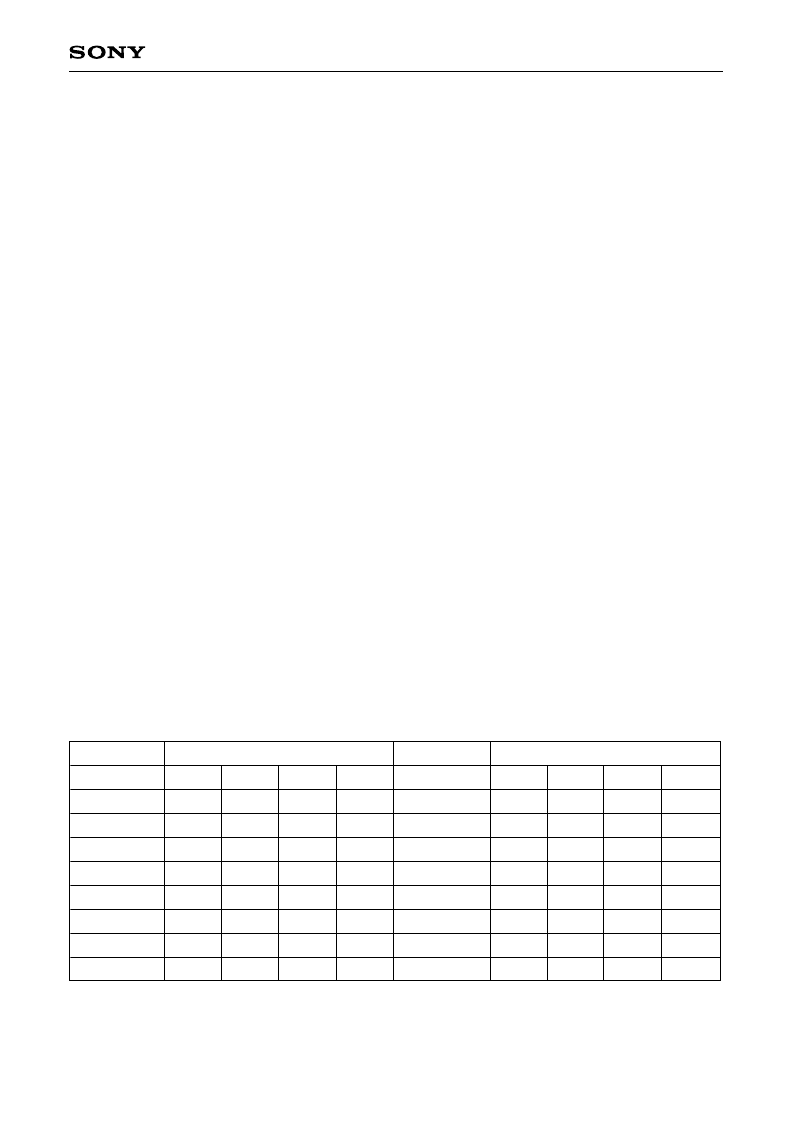
(m) SHP0, SHP1, SHP2, SHP3 and INV: CXA2112R sample-and-hold control
These control the sample-and-hold position of the CXA2112R (sample-and-hold driver). The SHP0, SHP1,
SHP2 and SHP3 setting data is reflected to SHA, SHB, SHC and SHD (Pins 157 to 160) as shown below.
Also, the INV setting data is output directly from the INV (Pin 161) output pin. See the specifications of the
CXA2112R for a detailed description of control methods. The initial values are SHP0 = 0h, SHP1 = 0h, SHP2 =
0h, SHP3 = 0h and INV = 0h.
Setting
SHP3 to SHP0
Output
Setting
Output
SHPA
SHPB
SHPC
SHPD
0000
0001
0010
0011
0100
0101
0110
0111
L
H
Z
Z
L
H
Z
Z
L
H
L
H
L
H
L
H
L
L
L
L
H
H
H
H
L
L
L
L
H
H
H
H
SHP3 to SHP0
SHPA
SHPB
SHPC
SHPD
1000
1001
1010
1011
1100
1101
1110
1111
L
H
Z
Z
L
H
Z
Z
L
H
L
H
L
H
L
H
Z
Z
Z
Z
Z
Z
Z
Z
L
L
L
L
H
H
H
H
Z: High impedance state
相關(guān)PDF資料 |
PDF描述 |
|---|---|
| CXD2470R | Timing Generator for Frame Readout CCD Image Sensor |
| CXD2475TQ | Reference Voltage and Driver IC for LCD |
| CXD2492R | RES, WW 1W 4.02 OHM 1% 90PPM |
| CXD2497R | Timing Generator for Frame Readout CCD Image Sensor |
| CXD2498R | Timing Generator for Frame Readout CCD Image Sensor |
相關(guān)代理商/技術(shù)參數(shù) |
參數(shù)描述 |
|---|---|
| CXD2470R | 制造商:SONY 制造商全稱(chēng):Sony Corporation 功能描述:Timing Generator for Frame Readout CCD Image Sensor |
| CXD2475TQ | 制造商:SONY 制造商全稱(chēng):Sony Corporation 功能描述:Reference Voltage and Driver IC for LCD |
| CXD2480R | 制造商:Sony Batteries 功能描述: |
| CXD2492R | 制造商:SONY 制造商全稱(chēng):Sony Corporation 功能描述:Timing Generator for Frame Readout CCD Image Sensor |
| CXD2497R | 制造商:SONY 制造商全稱(chēng):Sony Corporation 功能描述:Timing Generator for Frame Readout CCD Image Sensor |
發(fā)布緊急采購(gòu),3分鐘左右您將得到回復(fù)。