- 您現(xiàn)在的位置:買賣IC網(wǎng) > PDF目錄378482 > CY28326OCT (CYPRESS SEMICONDUCTOR CORP) FTG for VIA PT880 Serial Chipset PDF資料下載
參數(shù)資料
| 型號: | CY28326OCT |
| 廠商: | CYPRESS SEMICONDUCTOR CORP |
| 元件分類: | XO, clock |
| 英文描述: | FTG for VIA PT880 Serial Chipset |
| 中文描述: | 333.3 MHz, PROC SPECIFIC CLOCK GENERATOR, PDSO48 |
| 封裝: | SSOP-48 |
| 文件頁數(shù): | 10/23頁 |
| 文件大?。?/td> | 288K |
| 代理商: | CY28326OCT |
CY28326
Document #: 38-07616 Rev. *A
Page 10 of 23
Crystal Recommendations
The CY28326 requires a
Parallel Resonance Crystal.
Substituting a series resonance crystal will cause the
CY28326 to operate at the wrong frequency and violate the
ppm specification. For most applications there is a 300-ppm
frequency shift between series and parallel crystals due to
incorrect loading.
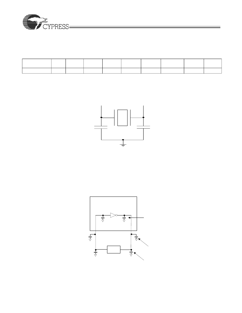
Crystal Loading
Crystal loading plays a critical role in achieving low ppm perfor-
mance. To realize low ppm performance, the total capacitance
the crystal will see must be considered to calculate the appro-
priate capacitive loading (CL).The following diagram shows a
typical crystal configuration using the two trim capacitors. An
important clarification for the following discussion is that the
trim capacitors are in series with the crystal not parallel. It’s a
common misconception that load capacitors are in parallel
with the crystal and should be approximately equal to the load
capacitance of the crystal. This is not true.
Calculating Load Capacitors
In addition to the standard external trim capacitors, trace
capacitance and pin capacitance must also be considered to
correctly calculate crystal loading. As mentioned previously,
the capacitance on each side of the crystal is in series with the
crystal.
This means the total capacitance on each side of the crystal
must be twice the specified crystal load capacitance (CL).
While the capacitance on each side of the crystal is in series
with the crystal, trim capacitors (Ce1,Ce2) should be calcu-
lated to provide equal capacitive loading on both sides.
As mentioned previously, the capacitance on each side of the
crystal is in series with the crystal. This mean the total capac-
itance on each side of the crystal must be 2 times the specified
load capacitance (CL).
While the capacitance on each side of the crystal is in series
with the crystal, trim capacitors(Ce1,Ce2) should be calcu-
lated to provide equal capacitative loading on both sides.
Table 7. Crystal Recommendations
Frequency
(Fund)
14.31818 MHz
Cut
Loading
Load Cap
Drive
(max.)
0.1 mW
Shunt Cap
(max.)
5 pF
Motional
(max.)
0.016 pF
Tolerance
(max.)
50 ppm
Stability
(max.)
50 ppm
Aging
(max.)
5 ppm
AT
Parallel
20 pF
Figure 1. Crystal Capacitive Clarification
XTAL
Ce2
Ce1
Cs1
Cs2
X1
X2
Ci1
Ci2
Clock Chip
(CY28326)
Trace
2.8pF
Trim
33pF
Pin
3 to 6p
Figure 2. Crystal Loading Example
相關(guān)PDF資料 |
PDF描述 |
|---|---|
| CY28326OXC | Single Pole Normally Open: 1-Form-A |
| CY28326OXCT | Single Pole Normally Open: 1-Form-A |
| CY28341-2 | Universal Clock Chip for VIA P4M/KT/KM400 DDR Systems |
| CY29962 | 2.5V/3.3V, 150-MHz Multi-Output Zero Delay Buffer |
| CY30 | Sensor interface for an inductive engine wheel speed single rotation sensor |
相關(guān)代理商/技術(shù)參數(shù) |
參數(shù)描述 |
|---|---|
| CY28326OXC | 制造商:Rochester Electronics LLC 功能描述:- Bulk |
| CY28326OXCT | 制造商:CYPRESS 制造商全稱:Cypress Semiconductor 功能描述:FTG for VIA PT880 Serial Chipset |
| CY28326SPC | 制造商:Cypress Semiconductor 功能描述: |
| CY28329 | 制造商:SPECTRALINEAR 制造商全稱:SPECTRALINEAR 功能描述:133 MHz Spread Spectrum Clock Synthesizer/Driver with Differential CPU Outputs |
| CY28329OXC | 功能描述:時鐘驅(qū)動器及分配 Intel CK-408B for Plumas chipset RoHS:否 制造商:Micrel 乘法/除法因子:1:4 輸出類型:Differential 最大輸出頻率:4.2 GHz 電源電壓-最大: 電源電壓-最小:5 V 最大工作溫度:+ 85 C 封裝 / 箱體:SOIC-8 封裝:Reel |
發(fā)布緊急采購,3分鐘左右您將得到回復(fù)。