- 您現(xiàn)在的位置:買賣IC網(wǎng) > PDF目錄295396 > CY7C4215-25AIT (CYPRESS SEMICONDUCTOR CORP) 512 X 18 OTHER FIFO, 15 ns, PQFP64 PDF資料下載
參數(shù)資料
| 型號(hào): | CY7C4215-25AIT |
| 廠商: | CYPRESS SEMICONDUCTOR CORP |
| 元件分類: | FIFO |
| 英文描述: | 512 X 18 OTHER FIFO, 15 ns, PQFP64 |
| 封裝: | 14 X 14 MM, PLASTIC, TQFP-64 |
| 文件頁(yè)數(shù): | 20/25頁(yè) |
| 文件大小: | 412K |
| 代理商: | CY7C4215-25AIT |
第1頁(yè)第2頁(yè)第3頁(yè)第4頁(yè)第5頁(yè)第6頁(yè)第7頁(yè)第8頁(yè)第9頁(yè)第10頁(yè)第11頁(yè)第12頁(yè)第13頁(yè)第14頁(yè)第15頁(yè)第16頁(yè)第17頁(yè)第18頁(yè)第19頁(yè)當(dāng)前第20頁(yè)第21頁(yè)第22頁(yè)第23頁(yè)第24頁(yè)第25頁(yè)

CY7C4425/4205/4215
CY7C4225/4235/4245
4
Maximum Ratings
(Above which the useful life may be impaired. For user guide-
lines, not tested.)
Storage Temperature
....................................65
°C to +150°C
Ambient Temperature with
Power Applied
.................................................55
°C to +125°C
Supply Voltage to Ground Potential
.................0.5V to +7.0V
DC Voltage Applied to Outputs
in High Z State
.....................................................0.5V to +7.0V
DC Input Voltage
.................................................3.0V to +7.0V
Output Current into Outputs (LOW)............................. 20 mA
Static Discharge Voltage ........................................... >2001V
(per MIL-STD-883, Method 3015)
Latch-Up Current ..................................................... >200 mA
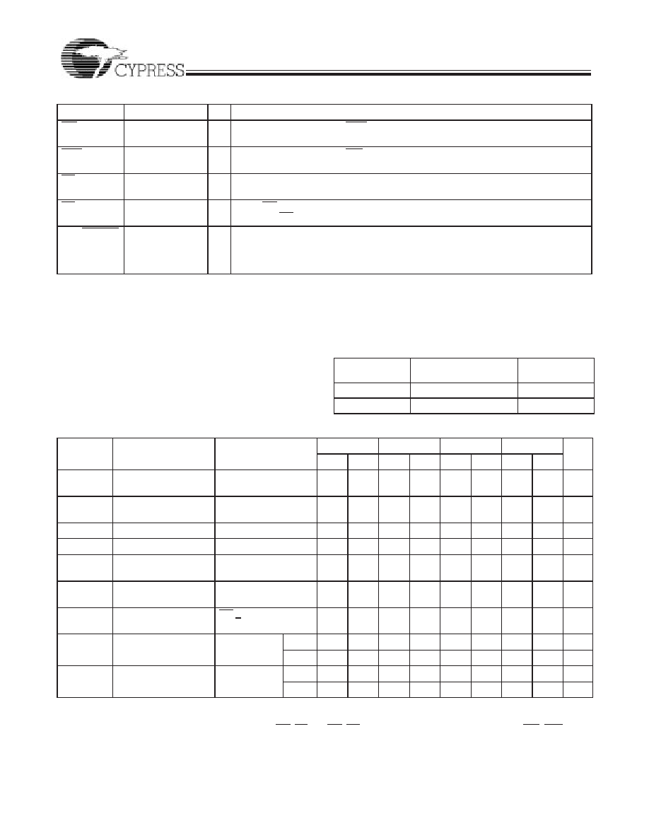
RXI
Read Expansion
Input
I
Cascaded - Connected to RXO of previous device.
Not Cascaded - Tied to VSS.
RXO
Read Expansion
Output
O
Cascaded - Connected to RXI of next device.
RS
Reset
I
Resets device to empty condition. A reset is required before an initial read or write
operation after power-up.
OE
Output Enable
I
When OE is LOW, the FIFO’s data outputs drive the bus to which they are con-
nected. If OE is HIGH, the FIFO’s outputs are in High Z (high-impedance) state.
VCC/SMODE Synchronous
Almost Empty/
Almost Full Flags
I
Dual-Mode Pin
Asynchronous Almost Empty/Almost Full flags - tied to VCC.
Synchronous Almost Empty/Almost Full flags - tied to VSS.
(Almost Empty synchronized to RCLK, Almost Full synchronized to WCLK.)
Pin Definitions (continued)
Signal Name
Description
I/O
Function
Operating Range
Range
Ambient
Temperature
VCC
Commercial
0
°C to +70°C
5V
± 10%
Industrial[1]
40
°C to +85°C
5V
± 10%
Electrical Characteristics Over the Operating Range[2]
Parameter
Description
Test Conditions
7C42X5-10
7C42X5-15
7C42X5-25
7C42X5-35
Min.
Max.
Min.
Max.
Min.
Max.
Min.
Max.
Unit
VOH
Output HIGH Voltage
VCC = Min.,
IOH = 2.0 mA
2.4
V
VOL
Output LOW Voltage
VCC = Min.,
IOL = 8.0 mA
0.4
V
VIH
[3]
Input HIGH Voltage
2.2
VCC
2.2
VCC
2.2
VCC
2.2
VCC
V
VIL
[3]
Input LOW Voltage
3.0
0.8
3.0
0.8
3.0
0.8
3.0
0.8
V
IIX
Input Leakage
Current
VCC = Max.
10
+10
10
+10
10
+10
10
+10
A
IOS
[4]
Output Short
Circuit Current
VCC = Max.,
VOUT = GND
90
mA
IOZL
IOZH
Output OFF,
High Z Current
OE > VIH,
VSS < VO < VCC
10
+10
10
+10
10
+10
10
+10
A
ICC2
[5]
Operating Current
VCC = Max.,
IOUT = 0 mA
Com’l
45
mA
Ind
50
mA
ISB
[6]
Standby Current
VCC = Max.,
IOUT = 0 mA
Com’l
10
mA
Ind
15
mA
Notes:
1.
TA is the “instant on” case temperature.
2.
See the last page of this specification for Group A subgroup testing information.
3.
The VIH and VIL specifications apply for all inputs except WXI, RXI. The WXI, RXI pin is not a TTL input. It is connected to either RXO, WXO of the
previous device or VSS.
4.
Test no more than one output at a time for not more than one second.
5.
Input signals switch from 0V to 3V with a rise/fall time less than 3 ns, clocks and clock enables switch at 20 MHz, while the data inputs switch at 10 MHz.
Outputs are unloaded.
6.
All input signals are connected to VCC. All outputs are unloaded.
相關(guān)PDF資料 |
PDF描述 |
|---|---|
| CY7C4205-10ACT | 256 X 18 OTHER FIFO, 8 ns, PQFP64 |
| CY7C4235V-25JC | 2K X 18 OTHER FIFO, 15 ns, PQCC68 |
| CY7C4241-35JC | 4K X 9 OTHER FIFO, 20 ns, PQCC32 |
| CY7C4421-15JIT | 64 X 9 OTHER FIFO, 10 ns, PQCC32 |
| CY7C4421-25AC | 64 X 9 OTHER FIFO, 15 ns, PQFP32 |
相關(guān)代理商/技術(shù)參數(shù) |
參數(shù)描述 |
|---|---|
| CY7C4215V-15ASC | 功能描述:IC SYNC FIFO MEM 512X18 64LQFP RoHS:否 類別:集成電路 (IC) >> 邏輯 - FIFO 系列:CY7C 標(biāo)準(zhǔn)包裝:90 系列:7200 功能:同步 存儲(chǔ)容量:288K(16K x 18) 數(shù)據(jù)速率:100MHz 訪問(wèn)時(shí)間:10ns 電源電壓:4.5 V ~ 5.5 V 工作溫度:0°C ~ 70°C 安裝類型:表面貼裝 封裝/外殼:64-LQFP 供應(yīng)商設(shè)備封裝:64-TQFP(14x14) 包裝:托盤 其它名稱:72271LA10PF |
| CY7C4215V-15ASXC | 功能描述:先進(jìn)先出 512 X18 LO VLTG SYNC 先進(jìn)先出 COM RoHS:否 制造商:IDT 電路數(shù)量: 數(shù)據(jù)總線寬度:18 bit 總線定向:Unidirectional 存儲(chǔ)容量:4 Mbit 定時(shí)類型:Synchronous 組織:256 K x 18 最大時(shí)鐘頻率:100 MHz 訪問(wèn)時(shí)間:10 ns 電源電壓-最大:3.6 V 電源電壓-最小:6 V 最大工作電流:35 mA 最大工作溫度:+ 85 C 封裝 / 箱體:TQFP-80 封裝: |
| CY7C4215V-25ASC | 制造商:Rochester Electronics LLC 功能描述:- Bulk |
| CY7C421-65AC | 制造商:Rochester Electronics LLC 功能描述:- Bulk |
| CY7C421-65JC | 制造商:Cypress Semiconductor 功能描述:512 X 9 OTHER FIFO, 65 ns, PQCC32 |
發(fā)布緊急采購(gòu),3分鐘左右您將得到回復(fù)。