- 您現(xiàn)在的位置:買賣IC網(wǎng) > PDF目錄93004 > D02PB905FS1P1FRUTH (HYPERTRONICS CORP) ULTEM, FEMALE, CIRCULAR CONNECTOR, CRIMP SOLDER, PLUG PDF資料下載
參數(shù)資料
| 型號: | D02PB905FS1P1FRUTH |
| 廠商: | HYPERTRONICS CORP |
| 元件分類: | 圓形連接器 |
| 英文描述: | ULTEM, FEMALE, CIRCULAR CONNECTOR, CRIMP SOLDER, PLUG |
| 文件頁數(shù): | 6/6頁 |
| 文件大小: | 18234K |
| 代理商: | D02PB905FS1P1FRUTH |
D Series
Dimensions are in inches [mm]
2 / 10
www.hypertronics.com
2 /9
www.hypertronics.com
Dimensions are in inches [mm]
D02
Coax or Power
and Signal
Receptacle seen from
mating side
Housing Options
Example Part Numbers1
Receptacle Panel Mount
Receptacle Cable
Plug
D02EEB905FR1C1FRUTHA
D02EPB905FR1C1FRUTHA
D02PB905MR1C1MRUT
Contact Options
See part number configurator on page 2/10
for complete ordering information.
Coax Crimp Socket – RRG 316, RG316DB
Coax Solder Cup Socket – RG405, T-Flex 405
Coax Crimp Pin – RG316, RG316DB
Coax Solder Cup Pin – RG405, T-Flex 405
Power Crimp Socket – 12 AWG
Power Crimp Pin – 12 AWG
Signal Crimp Socket – 22-26 AWG
Signal Solder Cup Socket – 22-26 AWG
Signal Crimp Pin – 22-26 AWG
Signal Solder Cup Pin – 22-26 AWG
Tools
Coax
Crimp Tool
HX3 (Outer)
AFM8 (Inner)
Crimp Die Set
T1958 (Outer) or
T2019 (Outer for
RG316DB)
Crimp Positioner
T1957 (Inner)
Removal Tool
T1982
Insertion Tool
–
Power
M309
–
T1981
T1982
–
Signal
AFM8
–
T870
–
T1215
NOTES:
1) H = Black Polyetherimide (High Temperature).
2) Available in Coax or Power and Signal.
Combination Connectors Coax or Power and Signal
Plating Reference
Male Pins:
T = 10in gold (min) over nickel (NA 0n D00)
TH = 50in gold (min) over nickel
Female Sockets:
TAH = 50in gold (min) over nickel on mating surface,
gold flash over nickel on termination
TABH = 50in gold (min) over nickel on mating surface,
tin lead over nickel on termination (D & B only)
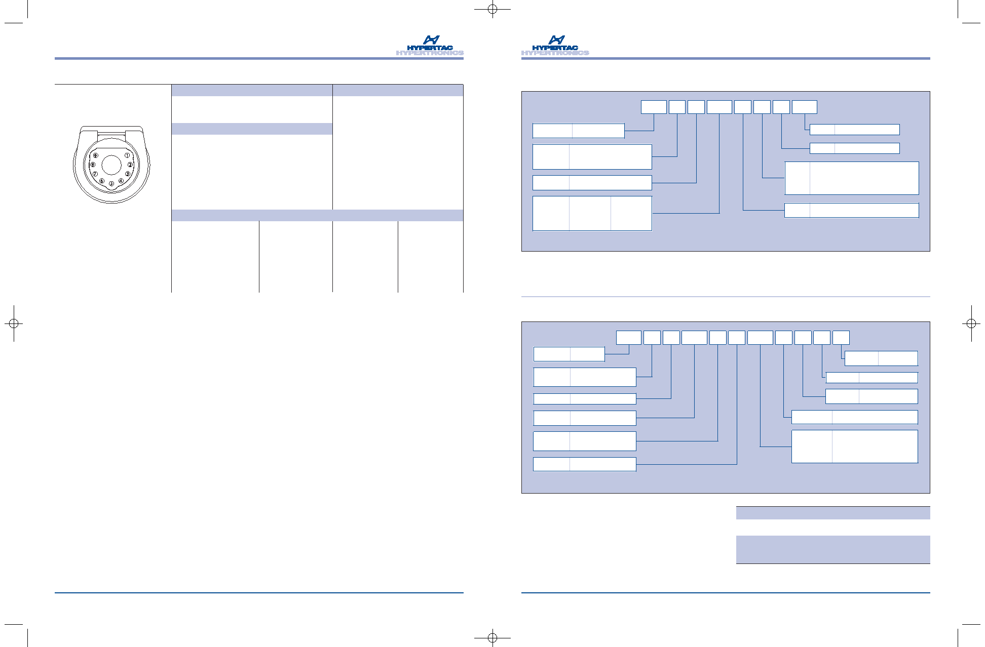
Ordering Information
D02
905
R
U
TH
B
M
R
1C1
M
P
Connector
Housing
D02
Coax Contact
Gender
M = Male
F = Female
Signal
Contact
Gender
M = Male
F = Female
Color
B = Black
Insulator
P = Plug
EE = Receptacle panel mount
EP = Receptacle cable mount
Contact
Arrangement
905
Terminal
Styles
R = Crimp
S = Solder
Terminal
Styles
R = Crimp
S = Solder
Plating
See Plating
Reference
Material
U = Ultem 1010R
Coaxial/Power
Cable Type
1C1 = RG316 (crimp)
1C2 = T-Flex 405, RG 405 (solder only,
cannot be used with crimp)
1C3 = RG316DB
1P1 = 12 AWG
D02 Coax or Power and Signal Ordering Information
*Note: Color code indicators are custom order only.
D01
306
U
TABH
B
F
R
P
Connector
Housing
D00, D01, D02
Contact
Gender
M = Male
F = Female
Main Body
Color
B = Black
Insulator
P = Plug
EE = Receptacle panel mount
EP = Receptacle cable mount
(EP Not available for 215/705 or 503 style)
Contact
Arrangement
D00 5 Pin = 503
D01 3 Pin = 306
D01 4 Pin = 406
D01 9 Pin = 904
D02 3 Pin = 315
D02 7 Pin = 706
D02 9 Pin = 906
D02 12 Pin = 125
D02 25 Pin = 2504
D02 Power/Signal
= 215/705
Terminal
Styles
R
= Crimp (shipped unassembled) D00 available
with "R" termination only (for crimp or solder)
RR = Crimp for 18-20 AWG (D01/306 and
D01/406 only. (shipped unassembled)
S
= Solder cup (shipped unassembled)
Plating
See Plating Reference
Material U = Ultem 1010R
*Note: Color code indicators are custom order only.
D00 panel mount receptacle with 6" pigtail leads pretermination = D00EEB-001
** Mounting options are available, see http://www.hypertronics.com/en/Products/circular-connectors/D-Series.aspx or call
(978) 568-0451 for more information.
HYP_DOseries_supl_4prt.qxd:Layout 1
12/24/09
8:19 AM
Page 12
相關(guān)PDF資料 |
PDF描述 |
|---|---|
| D02PB905FS1P1FSUTH | ULTEM, FEMALE, CIRCULAR CONNECTOR, SOLDER, PLUG |
| D02PB905FS1P1MRUTH | ULTEM, FEMALE AND MALE, CIRCULAR CONNECTOR, CRIMP SOLDER, PLUG |
| D02PB905FS1P1MSUTH | ULTEM, FEMALE AND MALE, CIRCULAR CONNECTOR, SOLDER, PLUG |
| D02PB905MR1C1FRUTH | ULTEM, MALE AND FEMALE, CIRCULAR CONNECTOR, CRIMP, PLUG |
| D02PB905MR1C1FSUTH | ULTEM, MALE AND FEMALE, CIRCULAR CONNECTOR, CRIMP SOLDER, PLUG |
相關(guān)代理商/技術(shù)參數(shù) |
參數(shù)描述 |
|---|---|
| D03000-000 | 制造商:TE Connectivity 功能描述:55 CABLE - Cable Rools/Shrink Tubing 制造商:TE Connectivity 功能描述:D03000-000 |
| D03009-000 | 制造商:TE Connectivity 功能描述:TX21AB00-1410H 制造商:TE Connectivity 功能描述:D03009-000 - Bulk |
| D0301410 | 制造商:HOUSTON WIRE AND CABLE 功能描述:Cable |
| D03021940G-00 | 制造商:未知廠家 制造商全稱:未知廠家 功能描述:SPECIFICATION FOR APPROVAL |
| D03047-000 | 制造商:TE Connectivity 功能描述:W-096-1202 |
發(fā)布緊急采購,3分鐘左右您將得到回復(fù)。