- 您現(xiàn)在的位置:買賣IC網(wǎng) > PDF目錄295418 > DAC1220LJ 12-Bit Digital-to-Analog Converter PDF資料下載
參數(shù)資料
| 型號(hào): | DAC1220LJ |
| 英文描述: | 12-Bit Digital-to-Analog Converter |
| 中文描述: | 12位數(shù)字到模擬轉(zhuǎn)換器 |
| 文件頁數(shù): | 2/14頁 |
| 文件大小: | 262K |
| 代理商: | DAC1220LJ |

Digital Interface
The DAC1054 has two interface modes a WRITE mode
and a READ mode The WRITE mode is used to convert a
10-bit digital input word into a voltage The READ mode is
used to read back the digital data that was sent to one or all
of the DACs The WRITE mode maximum clock rate is
10 MHz READ mode is limited to a 5 MHz maximum clock
rate These modes are selected by the appropriate setting
of the RDWR bit which is part of the instruction byte The
instruction byte precedes the data byte at the DI pin In both
modes a high level on the Start Bit (SB) alerts the DAC to
respond to the remainder of the input stream
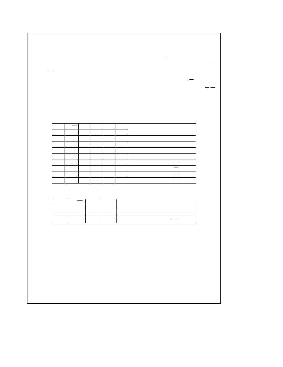
Table I lists the instruction set for the WRITE mode when
writing to only a single DAC and Table II lists the instruction
set for a global write Bits A0 and A1 select the DAC to be
written to The DACs are always written to MSB first All
DACs will be written to sequentially if the global bit (G) is
high DAC 1 is written to first then DACs 2 3 and 4 (in that
order) For a global write bits A0 and A1 of the instruction
byte are not required (see
Figure 2 timing diagram) If the
update bit (U) is high then the DAC output(s) will be updat-
ed on the rising edge of CS otherwise the new data byte
will be placed only in the input register Chip Select (CS)
must remain low for at least one clock cycle after the last
data bit has been entered (See
Figures 1 and 2 )
When the U bit is set low an asynchronous update of all the
DAC outputs can be achieved by taking AU low The con-
tents of the input registers are loaded into the DAC regis-
ters with the update occurring on the falling edge of AU CS
must be held high during an asynchronous update
All DAC registers will have their contents reset to all zeros
on power up
TABLE I WRITE Mode Instruction Set (Writing to a Single DAC)
SB
RDWR
G
U
A1
A0
Description
Bit
1
Bit
2
Bit
3 Bit
4 Bit
5 Bit
6
1
0
0000
Write DAC 1 no update of DAC outputs
1
0
0001
Write DAC 2 no update of DAC outputs
1
0
0010
Write DAC 3 no update of DAC outputs
1
0
0011
Write DAC 4 no update of DAC outputs
1
0
0100
Write DAC 1 update DAC 1 on CS rising edge
1
0
0101
Write DAC 2 update DAC 2 on CS rising edge
1
0
0110
Write DAC 3 update DAC 3 on CS rising edge
1
0
0111
Write DAC 4 update DAC 4 on CS rising edge
TABLE II WRITE Mode Instruction Set (Writing to all DACs)
SB
RDWR
GU
Description
Bit
1
Bit
2
Bit
3
Bit
4
1
0
1
0
Write all DACs no update of outputs
1
0
1
Write all DACs update all outputs on CS rising edge
10
相關(guān)PDF資料 |
PDF描述 |
|---|---|
| DAC1222LJ | 12-Bit Digital-to-Analog Converter |
| DAC1350X | DAC1350X 10BIT 75MSPS Quad-DAC|Data Sheet |
| DAC1353X | DAC1353X 1.2V 8BIT 2MSPS DAC|Data Sheet |
| DAC1391X | DAC1391X 2.5V 12BIT 80MSPS DAC|Data Sheet |
| DAC16BTC | 16-Bit Digital-to-Analog Converter |
相關(guān)代理商/技術(shù)參數(shù) |
參數(shù)描述 |
|---|---|
| DAC1221 | 制造商:BB 制造商全稱:BB 功能描述:16-Bit Low Power DIGITAL-TO-ANALOG CONVERTER |
| DAC1221E | 功能描述:數(shù)模轉(zhuǎn)換器- DAC 16-Bit Low Power RoHS:否 制造商:Texas Instruments 轉(zhuǎn)換器數(shù)量:1 DAC 輸出端數(shù)量:1 轉(zhuǎn)換速率:2 MSPs 分辨率:16 bit 接口類型:QSPI, SPI, Serial (3-Wire, Microwire) 穩(wěn)定時(shí)間:1 us 最大工作溫度:+ 85 C 安裝風(fēng)格:SMD/SMT 封裝 / 箱體:SOIC-14 封裝:Tube |
| DAC1221E/2K5 | 制造商:Rochester Electronics LLC 功能描述:D/A CONV, 16-BIT 3V - Bulk |
| DAC1221EG4 | 功能描述:數(shù)模轉(zhuǎn)換器- DAC 16B Delta-Sigma Low Power DAC RoHS:否 制造商:Texas Instruments 轉(zhuǎn)換器數(shù)量:1 DAC 輸出端數(shù)量:1 轉(zhuǎn)換速率:2 MSPs 分辨率:16 bit 接口類型:QSPI, SPI, Serial (3-Wire, Microwire) 穩(wěn)定時(shí)間:1 us 最大工作溫度:+ 85 C 安裝風(fēng)格:SMD/SMT 封裝 / 箱體:SOIC-14 封裝:Tube |
| DAC1221LCN | 制造商:n/a 功能描述:1221 |
發(fā)布緊急采購,3分鐘左右您將得到回復(fù)。