- 您現(xiàn)在的位置:買賣IC網(wǎng) > PDF目錄298987 > DDW1046 DC-DC REG PWR SUPPLY MODULE PDF資料下載
參數(shù)資料
| 型號(hào): | DDW1046 |
| 元件分類: | 電源模塊 |
| 英文描述: | DC-DC REG PWR SUPPLY MODULE |
| 封裝: | PLASTIC, DIP-6/16 |
| 文件頁數(shù): | 4/8頁 |
| 文件大?。?/td> | 274K |
| 代理商: | DDW1046 |
4
Test Configurations
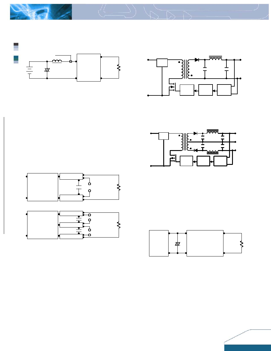
Input Reflected-Ripple Current Test
Setup
+Out
-Out
+Vin
-Vin
DC / DC
Converter
Load
Battery
+
Lin
+
Cin
To Oscilloscope
Current
Probe
Input reflected-ripple current is measured with a
inductor Lin (4.7uH) and Cin (220uF, ESR < 1.0 at
100 KHz) to simulate source impedance. Capacitor
Cin is to offset possible battery impedance. Current
ripple is measured at the input terminals of the
module and measurement bandwidth is 0-500 KHz.
Peak-to-Peak Output Noise Measurement
Scope measurement should be made by using a
BNC socket, measurement bandwidth is 0-20 MHz.
Position the load between 50 mm and 75 mm from
the DC/DC Converter. A Cout of 0.47uF ceramic
capacitor is placed between the terminals shown
below.
+Out
-Out
+Vin
-Vin
Single Output
DC / DC
Converter
Resistive
Load
Scope
Copper Strip
Cout
+Out
-Out
+Vin
-Vin
Dual Output
DC / DC
Converter
Resistive
Load
Scope
Copper Strip
Cout
Com.
Scope
Cout
Design & Feature Considerations
The DDW1000 circuit block diagrams are shown in
Figures 5 and 6.
PFM
Isolation
Ref.Amp
LC
Filter
+Vin
-Vin
-Vo
+Vo
Figure 5: Block diagram of DDW1000 single output
modules.
+Vo
PFM
Isolation
Ref.Amp
LC
Filter
+Vin
-Vin
Com
-Vo
Figure 6: Block diagram of DDW1000 dual output
modules.
Input Source Impedance
The power module should be connected to a low ac-
impedance input source. Highly inductive source
impedances can affect the stability of the power
module.
+
+Out
-Out
+Vin
-Vin
DC / DC
Converter
Load
DC Power
Source
+
-
Cin
In applications where power is supplied over long lines
and output loading is high, it may be necessary to use
a capacitor at the input to ensure startup.
Capacitor mounted close to the input of the power
module helps ensure stability of the unit, it is
recommended to use a good quality low Equivalent
Series Resistance (ESR < 1.0 at 100 KHz) capacitor
of a 8.2uF for the 5V input devices, a 3.3uF for the
12V input devices, and a 1.5uF for the 24V and 48V
devices.
相關(guān)PDF資料 |
PDF描述 |
|---|---|
| DDW1021 | DC-DC REG PWR SUPPLY MODULE |
| DDW1024 | DC-DC REG PWR SUPPLY MODULE |
| DDW1043 | DC-DC REG PWR SUPPLY MODULE |
| DDW1045 | DC-DC REG PWR SUPPLY MODULE |
| DDW1036 | DC-DC REG PWR SUPPLY MODULE |
相關(guān)代理商/技術(shù)參數(shù) |
參數(shù)描述 |
|---|---|
| DDW-CJD-R1 | 制造商:DOMINANT 制造商全稱:DOMINANT Semiconductors 功能描述:LED InGaN White |
| DDW-CJD-R2 | 制造商:DOMINANT 制造商全稱:DOMINANT Semiconductors 功能描述:LED InGaN White |
| DDW-CJD-RS2-1 | 制造商:DOMINANT 制造商全稱:DOMINANT Semiconductors 功能描述:LED InGaN White |
| DDW-CJD-S1 | 制造商:DOMINANT 制造商全稱:DOMINANT Semiconductors 功能描述:LED InGaN White |
| DDW-CJD-S2 | 制造商:DOMINANT 制造商全稱:DOMINANT Semiconductors 功能描述:LED InGaN White |
發(fā)布緊急采購,3分鐘左右您將得到回復(fù)。