- 您現(xiàn)在的位置:買賣IC網(wǎng) > PDF目錄376703 > DG200AK (Harris Corporation) CMOS Dual/Quad SPST Analog Switches PDF資料下載
參數(shù)資料
| 型號: | DG200AK |
| 廠商: | Harris Corporation |
| 英文描述: | CMOS Dual/Quad SPST Analog Switches |
| 中文描述: | CMOS雙/四路SPST模擬開關(guān) |
| 文件頁數(shù): | 2/5頁 |
| 文件大小: | 74K |
| 代理商: | DG200AK |

DG200A
2
Siliconix
S-52880—Rev. B, 28-Apr-97
Ordering Information
Temp Range
Package
Part Number
0 to 70 C
14-Pin Plastic DIP
DG200ACJ
–25 to 85 C
14-Pin CerDIP
DG200ABK
10-Pin Metal Can
DG200ABA
DG200AAK
14-Pin CerDIP
DG200AAK/883,
JM38510/12301BCA
–55 to 125 C
DG200AAA
10-Pin Metal Can
DG200AAA/883,
JM38510/12301BIC
14-Pin Sidebraze
JM38510/12301BCC
Absolute Maximum Ratings
V+ to V–
GND to V–
Digital Inputs
a
, V
S
, V
D
Current (Any Terminal) Continuous
Current S or D
(Pulsed at 1 ms, 10% Duty Cycle Max)
Storage Temperature
44 V
25 V
. . . . . . . . . . . . . . . . . . . . . . . . . . . . . . . . . . . . . . . . . . . . .
. . . . . . . . . . . . . . . . . . . . . . . . . . . . . . . . . . . . . . . . . . . .
. . . . . . . . . . . . . . . .
(V–) –2 V to (V+) +2 V or
30 mA, whichever occurs first
. . . . . . . . . . . . . . . . . . . . . .
30 mA
100 mA
. . . . . . . . . . . . . . . . . . .
. . . . . . . . . .
. . . . . . . . . . . . . . .
(AX, BX Suffix)
(CJ Suffix)
–65 to 150 C
–65 to 125 C
Power Dissipation (Package)
b
10-Pin Metal Can
c
14-Pin CerDIP
d
14-Pin Plastic DIP
e
450 mW
825 mW
470 mW
. . . . . . . . . . . . . . . . . . . . . . . . . . . . . . . . . . .
. . . . . . . . . . . . . . . . . . . . . . . . . . . . . . . . . . . . .
. . . . . . . . . . . . . . . . . . . . . . . . . . . . . . . . . .
Notes:
a.
Signals on S
X
, D
X
, or IN
X
exceeding V+ or V– will be clamped by
internal diodes. Limit forward diode current to maximum current
ratings.
All leads welded or soldered to PC Board.
Derate 6 mW/ C above 75 C
Derate 11 mW/ C above 75 C
Derate 6.5 mW/ C above 25 C
b.
c.
d.
e.
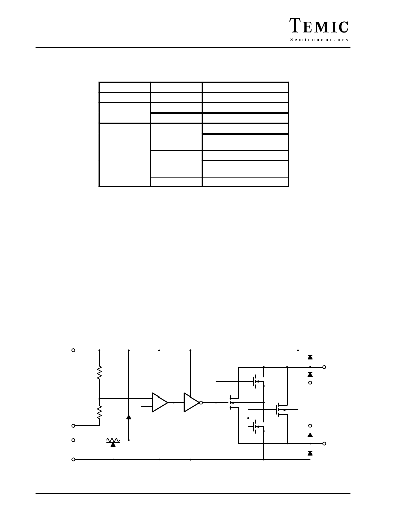
Schematic Diagram (Typical Channel)
Figure 1.
V+
IN
X
V–
GND
–
+
S
D
V–
V+
相關(guān)PDF資料 |
PDF描述 |
|---|---|
| DG200 | Dual Monolithic SPST CMOS Analog Switch |
| DG200A | Dual Monolithic SPST CMOS Analog Switch |
| DG200AAA | Dual Monolithic SPST CMOS Analog Switch |
| DG200AAK | LED, GREEN, CLEAR |
| DG200ABA | Dual Monolithic SPST CMOS Analog Switch |
相關(guān)代理商/技術(shù)參數(shù) |
參數(shù)描述 |
|---|---|
| DG200AK/883 | 制造商:未知廠家 制造商全稱:未知廠家 功能描述:SPST Analog Switch |
| DG200AK/883B | 制造商:HARRIS 制造商全稱:HARRIS 功能描述:CMOS Dual/Quad SPST Analog Switches |
| DG200AK/883B WAF | 制造商:Harris Corporation 功能描述: |
| DG200AK136 | 制造商:Rochester Electronics LLC 功能描述:- Bulk |
| DG200AL | 制造商:未知廠家 制造商全稱:未知廠家 功能描述:Interface IC |
發(fā)布緊急采購,3分鐘左右您將得到回復(fù)。