- 您現(xiàn)在的位置:買賣IC網(wǎng) > PDF目錄43025 > DPKB-101PX-7 (ITT CANNON) 101 CONTACT(S), MALE, MULTIWAY RACK AND PANEL CONN, CRIMP, RECEPTACLE PDF資料下載
參數(shù)資料
| 型號: | DPKB-101PX-7 |
| 廠商: | ITT CANNON |
| 元件分類: | 多腳機架和面板連接器 |
| 英文描述: | 101 CONTACT(S), MALE, MULTIWAY RACK AND PANEL CONN, CRIMP, RECEPTACLE |
| 文件頁數(shù): | 5/16頁 |
| 文件大小: | 494K |
| 代理商: | DPKB-101PX-7 |
www.ittcannon.com
87
Dimensions are shown in inches (millimeters).
Dimensions subject to change.
MIL-C-83733
DPK
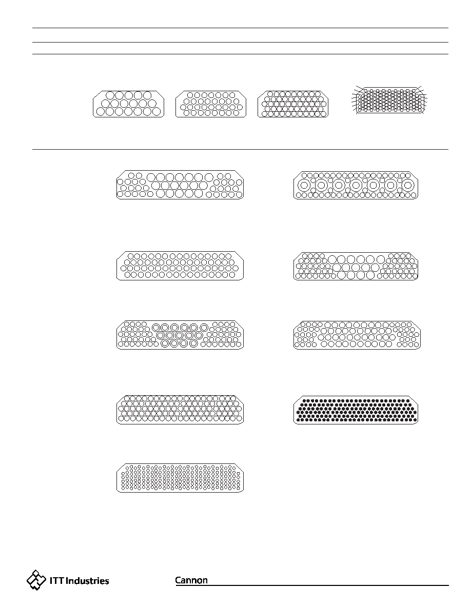
Contact Arrangements
DPKA
DPKB
Face View Pin Insert Shown
Layout
No. of Contacts
and Wire Size
Service Rating
18
18 #12
l
1
2
3
4
5
6
7
8
9
10
11
12
13
14
15
16
17
18
1
2
3
4
5
6
7
1
131
1
2
3
4
5
6
7
8
9
10
11
12
13
14
15
16
17
18
25
24
21
20
23
22
31
30
27
26
29
28
G
F
C
B
A
E
D
19
34
35
32
33
36
37
38
39
40
41
42
43
44
45
46
47
48
49
50
51
52
1
2
3
4
5
6
7
8
9
10
11
12
13
14
15
16
17
18
25
24
21
20
23
22
31
30
27
26
29
28
19
34
35
32
33
36
37
38
40
41
42
43
44
45
46
47
48
1
2
3
4
5
6
7
8
9
10
11
12
13
14
15
16
17
18
25
24
21
20
23
22
31
30
27
26
29
28
19
34
35
32
33
36
37
38
39
40
41
42
43
44
45
46
47
48
49
50
51
52
53
54
55
56
57
58
59
60
61
62
63
64
1
2
3
4
5
6
7
8
9
10
11
12
13
14
15
16
17
18
25
24
21
20
23
22
31 30
27 26
29 28
19
34
35
32
33
36
37
38
39
40
41
42
43
44
45
46
47
48
49
50
51
52
53
54
55
56
57
58
59
60
61
62
63
64
65
70
67
68
69
71
66
1
2
3
4
1
2
3
4
5
6
7
8
9
10
11
12
13
14
17
15
16
18
19
20
21
22
23
24
25
26
27
28
29
30
31
32
33
36
34
35
37
38
39
61
62
63
64
65
66
67
68
69
70
71
72
73
74
77
75
76
78
79
80
41 40
42
43
44
45
46
47
48
49
50
51
52
53
54
57
55
56
58
59
60
82 81
83
84
85
86
87
88
89
90
91
92
93
94
95
98
96
97
99
100
101
5
6
7
8
9
10
11
12
13
14
15
16
17
18
25
24
21
20
23
22
31 30
27 26
29 28
19
34
35
32
33
36
37
38
39
40
41
42
43
44
45
46
47
48
49
50
51
52
53
54
55
56
57
58
59
60
61
62
63
64
65
70
67
68
69
71
66
1
2
3
4
5
6
7
8
9
10
11
12
13
14
15
16
17
18
25
51
78
106
133
161
159
154
149
144
139
134
107
79
52
26
24
21 20
20
23
22
31
30
27
26
29
28
19
34
35
32
33
36
37
38
39
40
41
42
43
44
45
46
47
48
49
50
51
52
53
54
55
56
57
58
59
60
61
62
63
64
65
70
67
68
69
71
72
73
74
75
76
77
78
66
110
89
68
47
36
26
9
121
100
79
58
37
27
18
1
2
3
4
5
6
7
8
9
11
10
12
13
14
15
16
17
18
19
22 21 20
23
24
25
26
27
28
29
30
32 31
33
34
35
36
37
38
39
40
43 42 41
44
45
46
47
48
49
50
51
8
9
10
11
12
13
14
19
20
21
22
23
24
15
25
26
27
28
29
30
31
32
16
17
18
64
64 #16
l
101
101 #20
l
G185
185 #22D
M
161*
161 #22
1000 VDC
48
30 #16 (1,2,10-15,22-29,35-48),
18#12 (3-9,16-21,30-34)
59W7
52 #20 (1-52)
7 Coax. (A-G)
#20: 1500 Coax: 1000
l & 500 VDC (Coax)
71
56#20 (1-4,11-30,36-60,65-71
15 #12 (5-10,31-56,61-64)
l
71C15
56 #20 (1-4,11-30,36-60,65-71)
15 Shielded #12 (5-10, 31-35,61-64)
#20: 1500: #12 Shielded: 500
1&500 VDC (Coax)
78
38 #20 (1-4,14-21,32-38,51-57,
68-78),40 #16 (5-13, 22-31,
40-50,58-67
l
The 59W7 Layout is sold less coaxial contacts, se page 86 for contact part numbers.
32
32 #16
l
51
51 #20
l
G131
131 #220
M
Layout
No. of Contacts
and Wire Size
Service Rating
Layout
No. of Contacts
and Wire Size
Service Rating
Layout
No. of Contacts
and Wire Size
Service Rating
Layout
No. of Contacts
and Wire Size
Service Rating
Layout
No. of Contacts
and Wire Size
Service Rating
*P0S-ALINE DESIGN
In the 161 contact arrangement, the entire pin contact is recessed in and individual cavity in
the plug connector. The socket contact is exposed and extends from the connector receptacle
face. (Pin insulator accepts socket contacts.)
相關(guān)PDF資料 |
PDF描述 |
|---|---|
| DT06-3S | RECTANGULAR CONNECTOR, PLUG |
| DX-P-HA26-A1-1310 | 26 CONTACT(S), MALE, TELECOM AND DATACOM CONNECTOR, IDC, PLUG |
| DX-RN26S-350C-TB | 26 CONTACT(S), FEMALE, TELECOM AND DATACOM CONNECTOR, SURFACE MOUNT, RECEPTACLE |
| DX-RR26S-350C-TB | 26 CONTACT(S), FEMALE, TELECOM AND DATACOM CONNECTOR, SURFACE MOUNT, RECEPTACLE |
| E105MF1V3BE | TOGGLE SWITCH, SPDT, MOMENTARY, 0.02A, 20VDC, THROUGH HOLE-STRAIGHT |
相關(guān)代理商/技術(shù)參數(shù) |
參數(shù)描述 |
|---|---|
| DPKB-101SG | 制造商: 功能描述: 制造商:undefined 功能描述: |
| DPKB-101SG-12 | 制造商:ITT Interconnect Solutions 功能描述:DPKB-101SG-12 / 042941-0689 / Rack & Panel |
| DPKB-101SG-7 | 制造商:ITT Interconnect Solutions 功能描述:Conn Rack and Panel SKT 101 POS Crimp ST Panel Mount |
| DPKB-101SH-7 | 制造商:ITT Interconnect Solutions 功能描述:Conn Rack and Panel SKT 101 POS Crimp ST Panel Mount |
發(fā)布緊急采購,3分鐘左右您將得到回復。