- 您現(xiàn)在的位置:買賣IC網(wǎng) > PDF目錄257956 > DRT200U060E086 (MURATA MANUFACTURING CO LTD) CYLINDRICAL TYPE DIELECTRIC RESONATOR, 2660 MHz - 2880 MHz PDF資料下載
參數(shù)資料
| 型號: | DRT200U060E086 |
| 廠商: | MURATA MANUFACTURING CO LTD |
| 元件分類: | 介電諧振器 |
| 英文描述: | CYLINDRICAL TYPE DIELECTRIC RESONATOR, 2660 MHz - 2880 MHz |
| 文件頁數(shù): | 1/1頁 |
| 文件大小: | 62K |
| 代理商: | DRT200U060E086 |

Temp. Coeff.
Dielectric
Unloaded
Type
f
Constant
Q
(ppm/°C)
r (±0.5)
(at 7GHz)
A
–4
36.6
B–2
37.0
C
0
37.4
D
2
37.7
6000 min.
E
4
38.0
F
6
38.3
G
8
38.6
H
10
38.9
Part Number
Dr ± 0.05
Lr ± 0.05
Frequency
(mm)
Range* (GHz)
DRD046U
021
4.65
2.08
11.46 to 12.45
DRD051U
022
5.06
2.24
10.54 to 11.45
DRD055U
024
5.50
2.44
9.69 to 10.53
DRD060U
027
5.98
2.65
8.91 to 9.68
DRD065U
029
6.50
2.88
8.20 to 8.90
DRD071U
031
7.07
3.14
7.54 to 8.19
DRD077U
034
7.69
3.41
6.93 to 7.53
DRD084U
037
8.36
3.71
6.38 to 6.92
DRD091U
040
9.09
4.03
5.87 to 6.37
DRD099U
044
9.88
4.38
5.40 to 5.86
DRD107U
048
10.75
4.77
4.96 to 5.39
DRD117U
052
11.68
5.18
4.56 to 4.95
DRD127U
056
12.70
5.63
4.20 to 4.55
DRD138U
061
13.81
6.13
3.86 to 4.19
DRD150U
067
15.02
6.66
3.55 to 3.85
DRD163U
072
16.33
7.24
3.27 to 3.54
DRD178U
079
17.76
7.88
3.00 to 3.26
DRD193U
088
19.31
8.56
2.76 to 2.99
DRD210U
093
21.00
9.31
2.54 to 2.75
DRD228U 101
22.83
10.13
2.34 to 2.53
DRD248U 110
24.82
11.01
2.15 to 2.33
DRD270U 120
26.99
11.97
1.98 to 2.14
DRD293U 130
29.35
13.02
1.82 to 1.97
DRD319U 142
31.91
14.15
1.67 to 1.81
DRD347U 154
34.70
15.39
1.54 to 1.66
292
CG01-J
HIGH FREQUENCY DEVICES
DIELECTRIC RESONATORS–DRD & DRT
U Series
PART NUMBERING
TABLE 1: Q &
f
DIMENSIONS & FREQUENCY RANGE
GENERAL CHARACTERISTICS
I High unloaded Q — 6,000 min. at 7GHz.
I High dielectric constant —
r
38.
I Resonant frequency temperature coefficient from –4 to
+10ppm/°C.
I Accurate and repeatable dielectric constant (±0.5).
I Improved spurious response (spurious modes are further
removed from fundamental resonant frequency).
I Decoupled mounting on supports above substrate
maximizes operational Q.
DIMENSIONS & FREQUENCY RANGE
Part Number
Dr ± 0.05 dr ± 0.1 Lr ± 0.05
Frequency
(mm)
Range* (GHz)
DRT051U020 022
5.06
2.24
10.54 to 11.45
____________________________
_______________________
DRT055U020 024
5.50
2.44
9.69 to 10.53
____________________________
_______________________
DRT060U020 027
5.98
2.0
2.65
8.91 to 9.68
____________________________
_______________________
DRT065U020 029
6.50
2.88
8.20 to 8.90
____________________________
_______________________
DRT071U020 031
7.07
3.14
7.54 to 8.19
____________________________
_______________________
DRT077U020 034
7.69
3.41
6.93 to 7.53
DRT084U030 037
8.36
3.71
6.38 to 6.92
____________________________
_______________________
DRT091U030 040
9.09
3.0
4.03
5.87 to 6.37
____________________________
_______________________
DRT099U030 044
9.88
4.38
5.40 to 5.86
____________________________
_______________________
DRT105U030 046
10.50
4.60
5.08 to 5.51
DRT107U040 048
10.75
4.77
4.96 to 5.39
____________________________
_______________________
DRT117U040 052
11.68
5.18
4.56 to 4.95
____________________________
_______________________
DRT127U040 056
12.70
5.63
4.20 to 4.55
____________________________
_______________________
DRT138U040 061
13.81
6.13
3.86 to 4.19
____________________________
_______________________
DRT150U040 067
15.02
4.0
6.66
3.55 to 3.85
____________________________
_______________________
DRT163U040 072
16.33
7.24
3.27 to 3.54
____________________________
_______________________
DRT178U040 079
17.76
7.88
3.00 to 3.26
____________________________
_______________________
DRT193U040 086
19.31
8.56
2.76 to 2.99
____________________________
_______________________
DRT200U040 086
20.00
8.63
2.67 to 2.89
DRT200U040 086
20.00
6.0
8.63
2.66 to 2.88
Identification
f Tol. (ppm/°C)
—±2
A±1
B
±0.5
TABLE 2:
f
TOLERANCE
Note: *Frequency is measured under the condition: Lr/Lo = 0.33.
Q can be approximated by:
Q
≥
100,000
2.0 x fo + 2.6
fo = [GHz]
DRT
055
U
020
024
A
DRD = disk type
Outside diameter
Material
Inside diameter
f (Resonant Freq., T.C.)
Thickness
f tolerance
DRT = cylindrical type
(Dr)
type
(dr) for DRT only
as shown in Table 1
(Lr)
as shown in Table 2
Note: For actual dimension in mm, divide number by 10.
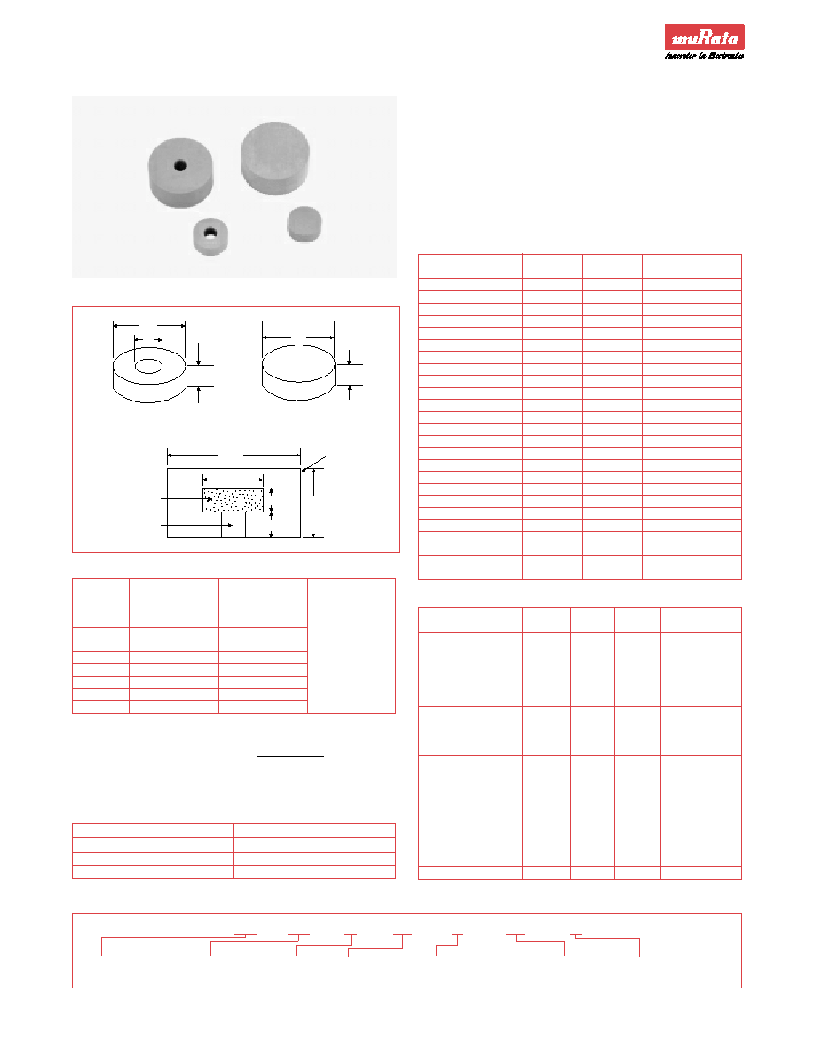
CONFIGURATION
Ls
Lr
Dr
Do
Lr
Dr
Lr
dr
Dr
Lo
Support
Resomics
Copper
Cavity
DRT
DRD
相關(guān)PDF資料 |
PDF描述 |
|---|---|
| DSX531S-FREQ-STBY1-TOL1-CL3 | QUARTZ CRYSTAL RESONATOR, 12 MHz - 35 MHz |
| DRT084V030F037B | CYLINDRICAL TYPE DIELECTRIC RESONATOR, 6850 MHz - 7340 MHz |
| DRT091B030E040B | CYLINDRICAL TYPE DIELECTRIC RESONATOR, 6850 MHz - 7480 MHz |
| DRT091U030E040A | CYLINDRICAL TYPE DIELECTRIC RESONATOR, 5870 MHz - 6370 MHz |
| DRT091U030F040 | CYLINDRICAL TYPE DIELECTRIC RESONATOR, 5870 MHz - 6370 MHz |
相關(guān)代理商/技術(shù)參數(shù) |
參數(shù)描述 |
|---|---|
| DRT-240 | 功能描述:DIN導軌式電源 RoHS:否 制造商:Mean Well 產(chǎn)品:Linear Supplies 商用/醫(yī)用:Commercial 輸出功率額定值:960 W 輸入電壓:180 VAC to 264 VAC, 254 VDC to 370 VDC 輸出端數(shù)量:1 輸出電壓(通道 1):48 V 輸出電流(通道 1): 輸出電壓(通道 2): 輸出電流(通道 2): 輸出電壓(通道 3): 輸出電流(通道 3): 尺寸:150 mm L x 110 mm W |
| DRT-240_0811 | 制造商:MEANWELL 制造商全稱:Mean Well Enterprises Co., Ltd. 功能描述:240W Three Phase Industrial DIN RAIL Power Supply |
| DRT-240_11 | 制造商:MEANWELL 制造商全稱:Mean Well Enterprises Co., Ltd. 功能描述:240W Three Phase Industrial DIN RAIL Power Supply |
| DRT-240-24 | 功能描述:DIN導軌式電源 24Vout 10A 240W 3 phase 340-550VAC RoHS:否 制造商:Mean Well 產(chǎn)品:Linear Supplies 商用/醫(yī)用:Commercial 輸出功率額定值:960 W 輸入電壓:180 VAC to 264 VAC, 254 VDC to 370 VDC 輸出端數(shù)量:1 輸出電壓(通道 1):48 V 輸出電流(通道 1): 輸出電壓(通道 2): 輸出電流(通道 2): 輸出電壓(通道 3): 輸出電流(通道 3): 尺寸:150 mm L x 110 mm W |
| DRT-240-48 | 功能描述:DIN導軌式電源 240W 48V 5A RoHS:否 制造商:Mean Well 產(chǎn)品:Linear Supplies 商用/醫(yī)用:Commercial 輸出功率額定值:960 W 輸入電壓:180 VAC to 264 VAC, 254 VDC to 370 VDC 輸出端數(shù)量:1 輸出電壓(通道 1):48 V 輸出電流(通道 1): 輸出電壓(通道 2): 輸出電流(通道 2): 輸出電壓(通道 3): 輸出電流(通道 3): 尺寸:150 mm L x 110 mm W |
發(fā)布緊急采購,3分鐘左右您將得到回復。