- 您現(xiàn)在的位置:買賣IC網(wǎng) > PDF目錄376962 > DS1921 High-Resolution Thermochron iButton PDF資料下載
參數(shù)資料
| 型號(hào): | DS1921 |
| 英文描述: | High-Resolution Thermochron iButton |
| 中文描述: | 高分辨率Thermochron iButton的 |
| 文件頁數(shù): | 6/44頁 |
| 文件大小: | 271K |
| 代理商: | DS1921 |
第1頁第2頁第3頁第4頁第5頁當(dāng)前第6頁第7頁第8頁第9頁第10頁第11頁第12頁第13頁第14頁第15頁第16頁第17頁第18頁第19頁第20頁第21頁第22頁第23頁第24頁第25頁第26頁第27頁第28頁第29頁第30頁第31頁第32頁第33頁第34頁第35頁第36頁第37頁第38頁第39頁第40頁第41頁第42頁第43頁第44頁
DS1921H/Z
6 of 44
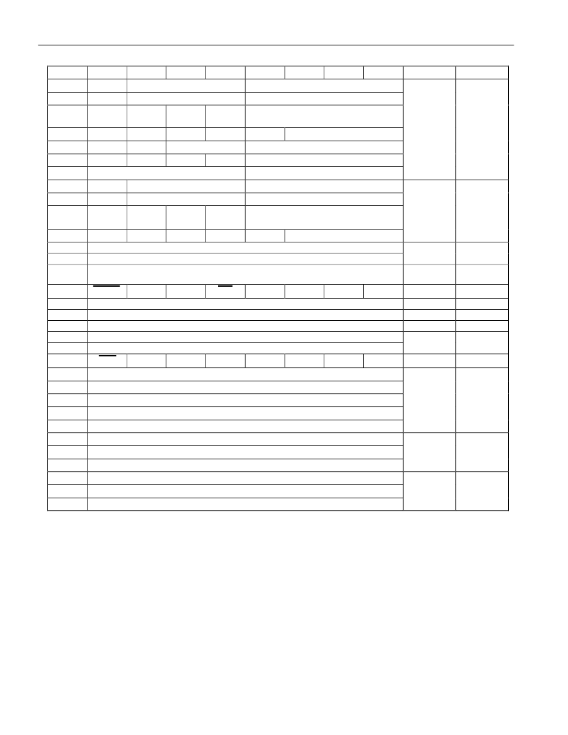
DS1921H/Z REGISTER PAGE MAP
Figure 6
ADDR
0200h
0201h
0202h
b7
0
0
0
b6
b5
b4
b3
b2
b1
b0
Function
Real-
Time
Clock
Registers
Real-
Time
Clock
Alarm
Registers
Temp.
Alarms
Sample
Rate
Control
(N/A)
(N/A)
Temp.
Start
Delay
Status
Mission
Time
Stamp
Mission
Samples
Counter
Device
Samples
Counter
Access*
10 Seconds
10 Minutes
20h.
AM/PM
0
Single Seconds
Single Minutes
12/24
10h.
Single Hours
R/W; R/W**
0203h
0204h
0205h
0206h
0207h
0208h
0209h
0
0
0
0
0
10 Years
10 Seconds Alarm
10 Minutes Alarm
12/24
10ha.
A/P
0
Temperature Low Alarm Threshold
Temperature High Alarm Threshold
Number of Minutes Between Temperature Conversions
0
0
Day of Week
Single Date
Single Months
Single Years
Single Seconds Alarm
Single Minutes Alarm
10 Date
0
CENT
10m.
MS
MM
MH
10h.
alm.
0
Single Hours Alarm
R/W; R/W**
020Ah
020Bh
020Ch
020Dh
MD
0
0
Day of Week Alarm
R/W; R/W**
R/W; R**
020Eh
020Fh
0210h
0211h
0212h
0213h
0214h
0215h
0216h
0217h
0218h
0219h
021Ah
021Bh
021Ch
021Dh
021Eh
021Fh
EOSC
EMCLR
0
EM
RO
TLS
THS
TAS
R/W; R/W**
R; R**
R; R**
R; R**
R/W; R/W**
R/W; R/W
R; R
R; R
R; R
(no function, reads 00h)
(no function, reads 00h)
Temperature Read Out (Forced Conversion)
Low Byte
High Byte
MEMCLR
MIP
SIP
Minutes
Hours
Date
Month
Year
Low Byte
Center Byte
High Byte
Low Byte
Center Byte
High Byte
TCB
0
TLF
THF
TAF
*The first entry in column ACCESS is valid between missions. The second entry shows the applicable
access mode while a mission is in progress.
**While a mission is in progress, these addresses can be read. The first attempt to write to these registers
(even read-only ones), however, will end the mission and overwrite selected writeable registers.
TIMEKEEPING
The RTC/alarm and calendar information is accessed by reading/writing the appropriate bytes in the
register page, address 200h to 206h. Note that some bits are set to 0. These bits will always read 0
regardless of how they are written. The contents of the time, calendar, and alarm registers are in the
Binary-Coded Decimal (BCD) format.
相關(guān)PDF資料 |
PDF描述 |
|---|---|
| DS1921H-F5 | High-Resolution Thermochron iButton |
| DS1921Z-F5 | High-Resolution Thermochron iButton |
| DS1963L-F5 | NVRAM (Battery Based) |
| DS1963S | SHA iButton |
| DS1971 | 256-Bit EEPROM iButton |
相關(guān)代理商/技術(shù)參數(shù) |
參數(shù)描述 |
|---|---|
| DS1921G | 制造商:未知廠家 制造商全稱:未知廠家 功能描述:Thermochron iButton |
| DS1921G_11 | 制造商:MAXIM 制造商全稱:Maxim Integrated Products 功能描述:Logs Up to 2048 Consecutive Temperature Thermochron iButton |
| DS1921G_1109 | 制造商:MAXIM 制造商全稱:Maxim Integrated Products 功能描述:Thermochron iButton |
| DS1921G_12 | 制造商:MAXIM 制造商全稱:Maxim Integrated Products 功能描述:Thermochron iButton |
| DS1921G-F5 | 功能描述:iButton RoHS:否 存儲(chǔ)類型:SRAM 存儲(chǔ)容量:512 B 組織: 工作電源電壓:3 V to 5.25 V 接口類型:1-Wire 最大工作溫度:+ 85 C 尺寸:17.35 mm x 5.89 mm 封裝 / 箱體:F5 MicroCan 制造商:Maxim Integrated |
發(fā)布緊急采購,3分鐘左右您將得到回復(fù)。