- 您現(xiàn)在的位置:買賣IC網(wǎng) > PDF目錄376982 > DS8617N-3 Prescaler/Frequency Divider PDF資料下載
參數(shù)資料
| 型號: | DS8617N-3 |
| 英文描述: | Prescaler/Frequency Divider |
| 中文描述: | 分頻器/分頻器 |
| 文件頁數(shù): | 3/6頁 |
| 文件大小: | 111K |
| 代理商: | DS8617N-3 |

AC Electrical Characteristics
V
CC
e
5V
g
10%, T
A
e b
30
§
C to
a
70
§
C
Symbol
Parameter
Conditions
Min
Max
Units
t
MODULUS
Modulus Set-Up Time
(Notes 4 and 5)
DS8615, DS8616
65
ns
R
IN
AC Input Resistance
V
IN
e
100 MHz and 50 mVrms
1.0
k
X
C
IN
Input Capacitance
V
IN
e
100 MHz and 50 mVrms
3
10
pF
Note 1:
‘‘Absolute Maximum Ratings’’ are those values beyond which the safety of the device cannot be guaranteed. Except for ‘‘Operating Temperature Range’’
they are not meant to imply that the devices should be operated at these limits. The table of ‘‘Electrical Characteristics’’ provides conditions for actual device
operation.
Note 2:
Unless otherwise specified min/max limits apply across the
b
30
§
C to
a
70
§
C temperature range.
Note 3:
All currents into device pins are shown as positive, out of device pins as negative, all voltages referenced to ground unless otherwise noted. All values
shown as max or min on absolute value basis.
Note 4:
t
MODULUS
e
the period of time the modulus control level must be defined prior to the positive transition of the prescaler output to ensure proper modulus
selection.
Note 5:
See Timing Diagrams.
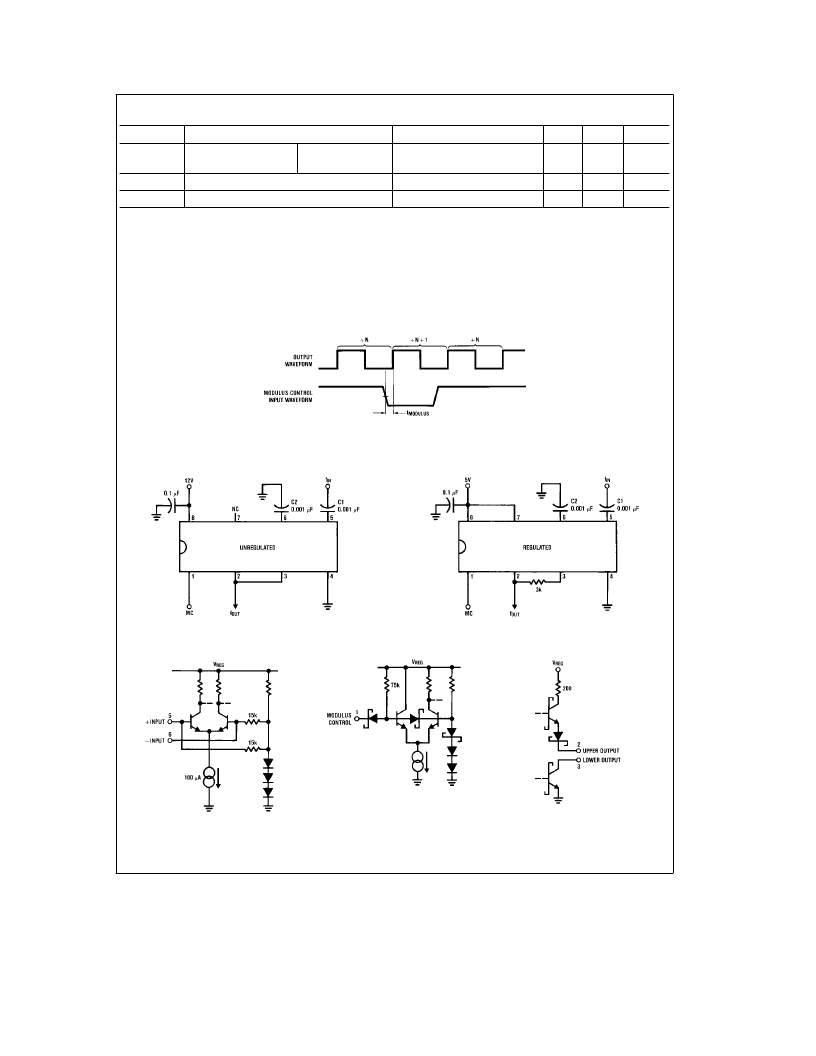
Timing Diagram
TL/F/5240–3
The logical state of the modulus control input just prior to the output’s rising edge will determine the modulus ratio of the device
immediately following that rising edge. The pulse width difference of N and N
a
1 operation occurs during the output
e
HI conditions.
Typical Applications
TL/F/5240–4
TL/F/5240–5
Schematic Diagrams
TL/F/5240–6
TL/F/5240–7
TL/F/5240–8
3
相關(guān)PDF資料 |
PDF描述 |
|---|---|
| DS8617N-4 | Prescaler/Frequency Divider |
| DS8621N | Prescaler/Frequency Divider |
| DS8622N | Prescaler/Frequency Divider |
| DS8626N | Prescaler/Frequency Divider |
| DS8629N | Prescaler/Frequency Divider |
相關(guān)代理商/技術(shù)參數(shù) |
參數(shù)描述 |
|---|---|
| DS8617N-3/A+ | 制造商:未知廠家 制造商全稱:未知廠家 功能描述:Prescaler/Frequency Divider |
| DS8617N-3/B+ | 制造商:未知廠家 制造商全稱:未知廠家 功能描述:Prescaler/Frequency Divider |
| DS8617N-4 | 制造商:未知廠家 制造商全稱:未知廠家 功能描述:Prescaler/Frequency Divider |
| DS8617N-4/A+ | 制造商:未知廠家 制造商全稱:未知廠家 功能描述:Prescaler/Frequency Divider |
| DS8617N-4/B+ | 制造商:未知廠家 制造商全稱:未知廠家 功能描述:Prescaler/Frequency Divider |
發(fā)布緊急采購,3分鐘左右您將得到回復(fù)。