- 您現(xiàn)在的位置:買賣IC網(wǎng) > PDF目錄171235 > DSS710D223S12-22 (MURATA MANUFACTURING CO LTD) 1 FUNCTIONS, 12 V, 7 A, DATA LINE FILTER PDF資料下載
參數(shù)資料
| 型號: | DSS710D223S12-22 |
| 廠商: | MURATA MANUFACTURING CO LTD |
| 元件分類: | 數(shù)據(jù)傳輸濾波器 |
| 英文描述: | 1 FUNCTIONS, 12 V, 7 A, DATA LINE FILTER |
| 文件頁數(shù): | 1/2頁 |
| 文件大小: | 78K |
| 代理商: | DSS710D223S12-22 |
CG01-I
257
EMI LEADED FILTERS
EMI SUPPRESSION FILTERS
VARISTOR-CAPACITOR
The DSS710 uses a capacitor element which provides the varistor
function. This varistor-capacitor not only works as a bypass
capacitor but also lets high-voltage surges flow to ground.
The varistor-capacitor used in the DSS710 has a 3-lead structure,
so that its high frequency functions are substantially better than
those of conventional capacitors. Furthermore, it is combined with
ferrite bead to form a T-shaped filter circuit that most effectively
suppresses EMI.
The DSS710 efficiently removes fast-rising transients and
high-frequency EMI above 50 or 60 MHz which conventional
capacitors and varistor-capacitors are incapable of removing.
Varistor-capacitors are used even where conventional EMI-filters
fail. They are self-healing and effective in circuits having
500-600V impulses.
PART NUMBERING SYSTEM
SPECIFICATIONS
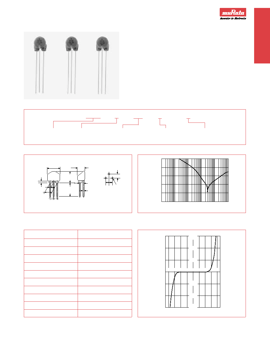
DIMENSIONS: mm
0
20
40
60
80
100
0.01 0.05 0.1
0.5
1
5
10
50 100 500 1000
Frequency (MHz)
Insertion
Loss
(dB)
DSS710
D
223S
12
—
22
SERIES
TEMPERATURE
CAPACITANCE
RATED
VARISTOR
CHARACTERISTICS
AND
VOLTAGE
TOLERANCE
TYPICAL INSERTION LOSS CHARACTERISTICS
F
10.5 max.
12.0 max.
2.5 ± 0.5
2.5 ± 0.2
Mounting Holes
F = 5.0 ± 0.5
F1 = 2.5 ± 0.5
F2 = 2.5 ± 0.2
DSS710 Series
Available as standard through authorized Murata Electronics Distributors.
Part Number
DSS710 D223 S 12-22
Capacitance
22000pF
%
DF
5.0% max.
Insulation Resistance
1M Ohms min.
IC (max.)
7 A
Rated Voltage
12VDC
Varistor Voltage
22VDC ± 20% (V1mA)
Voltage Nonlinear Factor
1.25 max. (V10mA/V1mA)
Temperature Characteristics
% (–25°C to +85°C)
Operating Temperature Range
–40°C to +100°C
Inductance
0.8 H x 2 (1kHz)
VOLTAGE – CURRENT CURVE
7.5 max.
F
1
2.5 max.
25.0 min.
3 x 0.8
F2 F2
0.65
Voltage (V)
Current
(mA)
+50
–20
+20
–30
–40 –30 –20 –10
0
10
20
30 40
300
200
100
–100
–200
–300
Note: Footprint for Bulk and Tape & Reel are different. Consult your local
Murata Electronics Sales Office.
EMI
LEADED
FIL
TERS
相關(guān)PDF資料 |
PDF描述 |
|---|---|
| DST9HB32E101Q55J | 1 FUNCTIONS, 250 V, 6 A, DATA LINE FILTER |
| DST9HB32E220Q55J | 1 FUNCTIONS, 250 V, 6 A, DATA LINE FILTER |
| DST9HB32E222Q55J | 1 FUNCTIONS, 250 V, 6 A, DATA LINE FILTER |
| DST9HB32E271Q55J | 1 FUNCTIONS, 250 V, 6 A, DATA LINE FILTER |
| DST9NC51H223Q55B | 1 FUNCTIONS, 50 V, 7 A, DATA LINE FILTER |
相關(guān)代理商/技術(shù)參數(shù) |
參數(shù)描述 |
|---|---|
| DSS71505A | 制造商:未知廠家 制造商全稱:未知廠家 功能描述:DIP 14 SERIES REED RELAYS |
| DSS71505B | 制造商:未知廠家 制造商全稱:未知廠家 功能描述:DIP 14 SERIES REED RELAYS |
| DSS71505C | 制造商:未知廠家 制造商全稱:未知廠家 功能描述:DIP 14 SERIES REED RELAYS |
| DSS71505S | 制造商:未知廠家 制造商全稱:未知廠家 功能描述:DIP 14 SERIES REED RELAYS |
| DSS715102 | 制造商:IXYS Integrated Circuits Division 功能描述:DSS715102 |
發(fā)布緊急采購,3分鐘左右您將得到回復(fù)。