- 您現(xiàn)在的位置:買賣IC網(wǎng) > PDF目錄223679 > DWR-5/2.65-3.3/3-D12L2 (CD TECHNOLOGIES INC) 2-OUTPUT 15 W DC-DC REG PWR SUPPLY MODULE PDF資料下載
參數(shù)資料
| 型號: | DWR-5/2.65-3.3/3-D12L2 |
| 廠商: | CD TECHNOLOGIES INC |
| 元件分類: | 電源模塊 |
| 英文描述: | 2-OUTPUT 15 W DC-DC REG PWR SUPPLY MODULE |
| 文件頁數(shù): | 5/9頁 |
| 文件大小: | 649K |
| 代理商: | DWR-5/2.65-3.3/3-D12L2 |
DSM/DWR Models
1 5 W , D U A L O U T P U T , M I X E D - V O L T A G E D C / D C C O N V E R T E R S
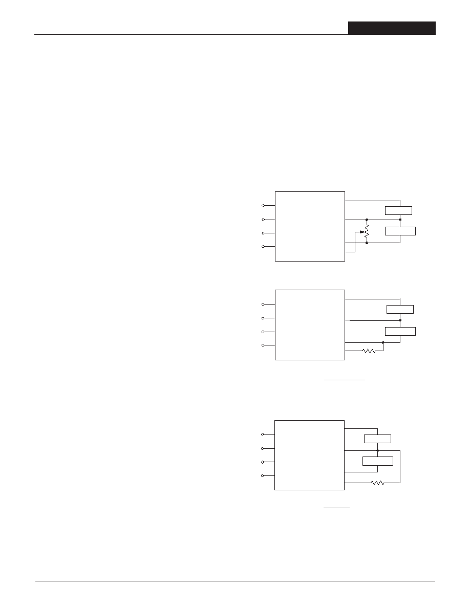
Trimming Output Voltages
The DSM/DWR converters have a trim capability (pin 9) that allow users to
adjust the output voltages ±5%. A trim adjustment will cause an equal percent-
age of change in both outputs. Adjustments to the output voltages can be
accomplished via a trim pot, Figure 3, or a single xed resistor as shown in
Figures 4 and 5. A single xed resistor can increase or decrease the output
voltage depending on its connection. Fixed resistors should have absolute
TCR's less than 100ppm/°C to minimize sensitivity to changes in temperature.
A single resistor connected from the Trim pin (pin 9) to the +3.3V Output (pin 8),
see Figure 4, will decrease the output voltages. A resistor connected from the
Trim pin (pin 9) to Output Return (pin 7) will increase the output voltages.
Trim adjustments greater than 5% can have an adverse effect on the convert-
er's performance and is not recommended.
Figure 3.Trim Connections Using A Trimpot
DOWN
3.3 – VO
RT
(k
) =
–14
2.49(VO – 1.234)
RT (k
) =
UP
VO – 3.3
–14
3.073
20k
5-22
Turns
+INPUT
+5V OUTPUT
+3.3V OUTPUT
TRIM
OUTPUT
RETURN
–INPUT
CASE
1
2
4
ON/OFF
CONTROL
3
5
9
7
+5V LOAD
+3.3V LOAD
8
+5V LOAD
+3.3V LOAD
R TRIM
DOWN
+INPUT
+5V OUTPUT
+3.3V OUTPUT
TRIM
OUTPUT
RETURN
–INPUT
CASE
1
2
4
ON/OFF
CONTROL
3
5
9
7
8
+5V LOAD
+3.3V LOAD
R TRIM
UP
+INPUT
+5V OUTPUT
+3.3V OUTPUT
TRIM
OUTPUT
RETURN
–INPUT
CASE
1
2
4
ON/OFF
CONTROL
3
5
9
7
8
Figure 4. Decrease Output Voltage Trim Connections
Using A Fixed Resistor
Figure 5. Increase Output Voltage Trim Connections
Using A Fixed Resistor
Accuracy of adjustment is subject to tolerances or resistor values and
factory-adjusted output accuracy. VO = desired output voltage.
DOWN
3.3 – VO
RT
(k
) =
–14
2.49(VO – 1.234)
RT (k
) =
UP
VO – 3.3
–14
3.073
5V & 3.3V Regulation
The XWR Series converters are designed such that both the 5V and 3.3V
outputs share a common regulation feedback control loop. Though the feed-
back loop is inuenced by both outputs, the 3.3 Volt output is dominant. As
a result, the 3.3 Volt regulation (0.5%) is superior to the 5 Volt regulation
(1.5%).
The converters are specied for load regulation of minimum (250mA) to
100% loading. All models are stable under no-load conditions, but operation
below minimum load mandates an increase in the regulation tolerance of
±0.5% for 3.3 Volt output and an increase of ±1% for the 5 Volt output. A
slight increase in switching noise may also be observed for operation below
minimum loading. Operation with a full load on 3.3 Volt output and light to no
load on 5 Volt output is the most demanding for +5V regulation.
Filtering and Noise Reduction
The XWR Series Converters achieve their rated ripple and noise specica-
tions with the use of 0.47F ceramic in parallel with 100F tantalum output
capacitors. In critical applications, input/output noise may be further reduced
by installing additional external I/O capacitors. Input capacitors should be
selected for bulk capacitance, low ESR and high rms-ripple-current ratings.
Output capacitors should be selected for low ESR and appropriate frequency
response. All caps should have appropriate voltage ratings and be located as
close to the converter as possible.
Thermal Shutdown
These XWR converters are equipped with Thermal Shutdown Circuitry. If
the internal temperature of the DC/DC converter rises above the designed
operating temperature, a precision temperature sensor will power down the
unit. When the internal temperature decreases below the threshold of the
temperature sensor, the units will self start.
Current Limiting
When power demands from either output fall within 120% to 190% of the
rated output current, the DC/DC converter will go into a current limiting
mode. In this condition, both output voltages will decrease proportionately
with increases in output current, thereby maintaining a somewhat constant
power dissipation.
This is commonly referred to as power limiting. Current limit inception is
dened as the point where the full-power output voltage falls below the
specied tolerance. If the load current being drawn from the converter is
signicant enough, the unit will go into a short circuit condition. See “Short
Circuit Condition.”
Short Circuit Condition
When a converter is in current limit mode the output voltages will drop as
the output current demand increases. If the output voltage drops too low, the
magnetically coupled voltage used to develop primary side voltages will also
drop, thereby shutting down the PWM controller.
Following a time-out period of 5 to 15 milliseconds, the PWM will restart,
causing the output voltages to begin ramping to their appropriate values. If
the short-circuit condition persists, another shutdown cycle will be initiated.
This on/off cycling is referred to as “hiccup” mode. The hiccup cycling
reduces the average output current, thereby preventing internal temperatures
from rising to excessive levels. The modules are capable of enduring an
indenite short circuit output condition.
5
相關PDF資料 |
PDF描述 |
|---|---|
| DWR-5/2.65-3.3/3-D48L1 | 2-OUTPUT 15 W DC-DC REG PWR SUPPLY MODULE |
| DX21DFIG01 | 1575.42 MHz(Tx), 873.5 MHz(Rx), DUPLEXER |
| DX21TFCD02 | 2630 MHz(Tx), 859 MHz(Rx), DUPLEXER |
| DZ11A91-ND205-4F | 15 CONTACT(S), FEMALE, D SUBMINIATURE CONNECTOR, SOLDER |
| DZ23C2V7 | 2.7 V, 0.3 W, SILICON, UNIDIRECTIONAL VOLTAGE REGULATOR DIODE |
相關代理商/技術參數(shù) |
參數(shù)描述 |
|---|---|
| DWR70A30 | 制造商:SANREX 制造商全稱:SanRex Corporation 功能描述:DIODE MODULE |
| DWR70A40 | 制造商:SANREX 制造商全稱:SanRex Corporation 功能描述:DIODE MODULE |
| DWR70BB30 | 制造商:SANREX 制造商全稱:SanRex Corporation 功能描述:DIODE MODULE |
| DWR70BB40 | 制造商:SANREX 制造商全稱:SanRex Corporation 功能描述:DIODE MODULE |
| DWRA 220A | 制造商:Schneider Electric 功能描述:PHASE CTRL RLY, DIN RAIL, 3x220VAC |
發(fā)布緊急采購,3分鐘左右您將得到回復。