- 您現(xiàn)在的位置:買賣IC網(wǎng) > PDF目錄299014 > E-L9935013TR (STMICROELECTRONICS) STEPPER MOTOR CONTROLLER, 2.5 A, PDSO20 PDF資料下載
參數(shù)資料
| 型號: | E-L9935013TR |
| 廠商: | STMICROELECTRONICS |
| 元件分類: | 運(yùn)動控制電子 |
| 英文描述: | STEPPER MOTOR CONTROLLER, 2.5 A, PDSO20 |
| 封裝: | ROHS COMPLIANT, POWER, MO-166, SOP-20 |
| 文件頁數(shù): | 11/29頁 |
| 文件大小: | 311K |
| 代理商: | E-L9935013TR |
第1頁第2頁第3頁第4頁第5頁第6頁第7頁第8頁第9頁第10頁當(dāng)前第11頁第12頁第13頁第14頁第15頁第16頁第17頁第18頁第19頁第20頁第21頁第22頁第23頁第24頁第25頁第26頁第27頁第28頁第29頁
L9935
Functional description
5.12
Limitation of the diagnosis
The diagnosis depends on either detecting an overcurrent of more than typically 1.8A
through the source transistor or on not detecting a flyback pulse, or on detecting severe
overcurrents of the sink transistor immediately after turn on.
●
Small currents bypassing the load will not be detected.
●
In the low current range (hold current) the flyback pulse (especially commutating
against the supply voltage after changing phase) may (depending on the inductivity of
the stepper motor windings) be too short to be detected correctly. For this reason
diagnosis using the flyback pulse is blanked at phase reversal at hold current.
●
In the low current range (hold current) the current capability of the bridge is reduced on
purpose. Short to VS may not be detected. In stead the bridge may just chop like
normal operation.
●
Flyback pulse detection is not blanked during PWM regulation at hold current (here
commutation voltage is less than 1V thus providing a longer pulse duration.) This
however should be taken in account using stepper motors with low inductivity (less than
0.5mH). Using motors with such a low inductivity the flyback voltage in hold mode may
decay too fast.
●
Motors with extremely low ohmic resistance tend to pump up the current because
current decay during flyback approaches zero while at bridge turn on the current will
increase. This may lead to overcurrent detection. We suggest to use stepper motors
with an ohmic resistance of approximately 3W or more.
Partial shorts of windings or shorts of stepper motors with coils in series may still yield a
flyback pulses that are accepted by the diagnosis as a proper signal.
At stepping rates faster than 1ms/data transfer error flags indicating a short should be used
to initiate a pause of at least 1ms to allow the power bridges to cool down again.
5.13
Serial data interface (SPI)
The serial data interface itself consists of the pins SCL (serial clock), SDI (serial data input)
and SDO (serial data output).
To especially support bus controlled applications the additional signals EN (chip enable not)
and CSN (chip select not) are available.
5.13.1
Startup of the Serial Data Interface
Falling slope of EN activates the device. After ten.sck the device is ready to work.
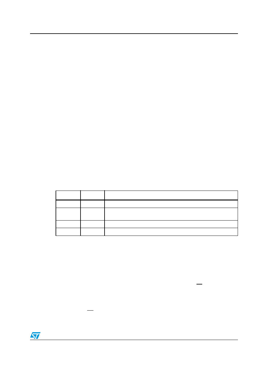
Table 7.
Insert Title Here
Error 1 bit7 Error 2 bit6
Description
H
Normal operation
L
H
Short to VS (sink overload immediately after turn on) shorted load (no
flyback) open load (no flyback)
H
L
short to gnd (source overload, missing flyback is masked)
L
over temperature pre alarm
相關(guān)PDF資料 |
PDF描述 |
|---|---|
| E1L33-3BOA6-02 | T-1 SINGLE COLOR LED, BLUE, 3 mm |
| E1L35-3G0A7-02 | T-1 SINGLE COLOR LED, GREEN, 3 mm |
| E1L35-3G0A5-02 | T-1 SINGLE COLOR LED, GREEN, 3 mm |
| E1SAD20-32.6864MTR | QUARTZ CRYSTAL RESONATOR, 32.6864 MHz |
| E1SBA18-11.0592MTR | QUARTZ CRYSTAL RESONATOR, 11.0592 MHz |
相關(guān)代理商/技術(shù)參數(shù) |
參數(shù)描述 |
|---|---|
| E-L9997ND | 制造商:STMicroelectronics 功能描述:MOSFET DRVR 2.2A 2-OUT HALF BRDG NON-INV 20SOIC - Rail/Tube |
| E-L9997ND013TR | 制造商:STMicroelectronics 功能描述:MOSFET DRVR 2.2A 2-OUT HALF BRDG NON-INV 20SOIC - Tape and Reel |
| ELA110-14-10 | 制造商:Misc 功能描述: |
| ELA110-14-25 | 制造商:Misc 功能描述: |
| ELA114-08-10 | 制造商:Misc 功能描述: |
發(fā)布緊急采購,3分鐘左右您將得到回復(fù)。