- 您現(xiàn)在的位置:買(mǎi)賣(mài)IC網(wǎng) > PDF目錄362644 > EL6201CYZ-T13 (INTERSIL CORP) Low Power 430MHz HFM Oscillator w/Disable PDF資料下載
參數(shù)資料
| 型號(hào): | EL6201CYZ-T13 |
| 廠商: | INTERSIL CORP |
| 元件分類: | 其它接口 |
| 英文描述: | Low Power 430MHz HFM Oscillator w/Disable |
| 中文描述: | SPECIALTY INTERFACE CIRCUIT, PDSO8 |
| 封裝: | LEAD FREE, MSOP-8 |
| 文件頁(yè)數(shù): | 8/8頁(yè) |
| 文件大小: | 175K |
| 代理商: | EL6201CYZ-T13 |
8
All Intersil U.S. products are manufactured, assembled and tested utilizing ISO9000 quality systems.
Intersil Corporation’s quality certifications can be viewed at www.intersil.com/design/quality
Intersil products are sold by description only. Intersil Corporation reserves the right to make changes in circuit design, software and/or specifications at any time without
notice. Accordingly, the reader is cautioned to verify that data sheets are current before placing orders. Information furnished by Intersil is believed to be accurate and
reliable. However, no responsibility is assumed by Intersil or its subsidiaries for its use; nor for any infringements of patents or other rights of third parties which may result
from its use. No license is granted by implication or otherwise under any patent or patent rights of Intersil or its subsidiaries.
For information regarding Intersil Corporation and its products, see www.intersil.com
adjust initial operating points, but they should be replaced
with fixed resistors for further testing.
External voltage sources can be coupled to the R
AMP
and
R
FREQ
pins to effect frequency or amplitude modulation or
adjustment. It is recommended that a coupling resistor be
installed in series with the control voltage and mounted
directly next to the EL6201 pin. This will keep the inevitable
high-frequency noise of the EL6201’s local environment from
propagating to the modulation source, and it will keep
parasitic capacitance at the EL6201 pin minimized.
Both inputs have several megahertz of bandwidth for analog
modulation. The output enable pin can be used to pass
digital modulation up to about 20Mbit/sec rates.
Power Dissipation Considerations
Supply current can be predicted by the equation:
The 12mA quantity represents the operating DC current of
the EL6201. This is also the current drawn from the supply
during output disable. The I
OUT
quantity is based on a
typical 50% duty cycle of output pull-up current, and the fact
that the peak-to-peak output current is about twice the pull-
up or pull-down currents. The V
S
quantity is due to CV
2
F
losses within the circuit, and the 8*10
-12
quantity represents
internal capacitances that must be slewed at the operating
frequency. The 1.6V offset is a curve fit to measured data.
The internal die temperature operating range is -40°C to
+125°C. Internal temperature is equal to the ambient
temperature plus power dissipated times the thermal
resistance of the mounted package,
θ
JA
. For a mounted
MSOP-8 package,
θ
JA
is 206°C/W. The SOT-23 package
has a
θ
JA
of 256°C/W.
Power-Down with the SOT-23 Package
The supply current of the EL6201 is low enough so that a
logic output can simply provide the supply current of the part
and effect power-down. This is most useful using the EL6201
in the SOT-23 package, which has no enable pin.
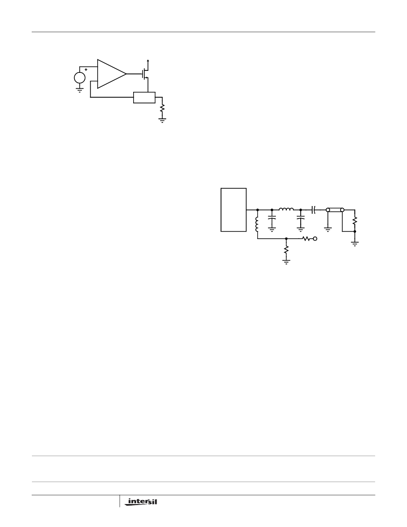
RF Applications
The EL6201 can easily interface to reactive loads, and is
adequate as a short-range modulated transmitter.
Remembering that the output circuitry looks like current
sources, impedance matching becomes a matter of
transforming the load impedance to an appropriate load line
for the EL6201. Also important is maintaining correct DC
bias voltage on the output. Since the output will have a net
DC current, capacitor coupling would allow the DC level to
drift toward a supply rail and increase output harmonic
products. In cases where such harmonics are important,
Figure 25 shows coupling the EL6201 output to a 50
load:
Digital Clock Applications
The EL6201 can be used as a digital clock source. If
unloaded, the output will simply traverse ground to V
S
. It is
recommended that the V
S
supply be isolated from the main
digital supply with an inductor or resistor, whose value is
chosen to drop about 250mV. In this way logic noise can be
isolated by the series component and the EL6201 local
bypass.
The rise- and fall-time of the output will be equal to
V
S
/(C
LOAD
*I
OUTp-p
/2). The output current should be the
smallest that can set an output rise-time, in the interest of
lowest dissipation.
The jitter is about 0.7% of period, RMS.
-
+
PIN
V
REF
FIGURE 24. R
FREQ
AND R
AMP
PIN INTERFACE
I
S
12mA
I
+
4
V
S
(
- 1.6V
)
FREQ
8
10
×
×
×
+
------------------------------------------------------------------------------------------------
=
I
OUT
EL6201
L
CHOKE
C1
C2
R1
V
S
R2
L
0.001μF
50
LOAD
FIGURE 25. TUNED INTERFACE TO 50
LEAD
EL6201
相關(guān)PDF資料 |
PDF描述 |
|---|---|
| EL6201CYZ-T7 | Low Power 430MHz HFM Oscillator w/Disable |
| EL6202 | Laser Driver Oscillator |
| EL6202CW-T7 | Laser Driver Oscillator |
| EL6202CW-T7A | Laser Driver Oscillator |
| EL6203 | Laser Driver Oscillator |
相關(guān)代理商/技術(shù)參數(shù) |
參數(shù)描述 |
|---|---|
| EL6201CYZ-T7 | 制造商:INTERSIL 制造商全稱:Intersil Corporation 功能描述:Low Power 430MHz HFM Oscillator with Disable |
| E-L6201PS | 功能描述:馬達(dá)/運(yùn)動(dòng)/點(diǎn)火控制器和驅(qū)動(dòng)器 DMOS Full Bridge RoHS:否 制造商:STMicroelectronics 產(chǎn)品:Stepper Motor Controllers / Drivers 類型:2 Phase Stepper Motor Driver 工作電源電壓:8 V to 45 V 電源電流:0.5 mA 工作溫度:- 25 C to + 125 C 安裝風(fēng)格:SMD/SMT 封裝 / 箱體:HTSSOP-28 封裝:Tube |
| E-L6201PSTR | 功能描述:馬達(dá)/運(yùn)動(dòng)/點(diǎn)火控制器和驅(qū)動(dòng)器 DMOS Full Bridge RoHS:否 制造商:STMicroelectronics 產(chǎn)品:Stepper Motor Controllers / Drivers 類型:2 Phase Stepper Motor Driver 工作電源電壓:8 V to 45 V 電源電流:0.5 mA 工作溫度:- 25 C to + 125 C 安裝風(fēng)格:SMD/SMT 封裝 / 箱體:HTSSOP-28 封裝:Tube |
| EL6202 | 制造商:INTERSIL 制造商全稱:Intersil Corporation 功能描述:Laser Driver Oscillator |
| E-L6202 | 功能描述:馬達(dá)/運(yùn)動(dòng)/點(diǎn)火控制器和驅(qū)動(dòng)器 DMOS Full Bridge RoHS:否 制造商:STMicroelectronics 產(chǎn)品:Stepper Motor Controllers / Drivers 類型:2 Phase Stepper Motor Driver 工作電源電壓:8 V to 45 V 電源電流:0.5 mA 工作溫度:- 25 C to + 125 C 安裝風(fēng)格:SMD/SMT 封裝 / 箱體:HTSSOP-28 封裝:Tube |
發(fā)布緊急采購(gòu),3分鐘左右您將得到回復(fù)。