- 您現(xiàn)在的位置:買(mǎi)賣(mài)IC網(wǎng) > PDF目錄362651 > EL7562CUZ (INTERSIL CORP) Monolithic 2Amp DC-DC Step-Down Regulator PDF資料下載
參數(shù)資料
| 型號(hào): | EL7562CUZ |
| 廠商: | INTERSIL CORP |
| 元件分類: | 穩(wěn)壓器 |
| 英文描述: | Monolithic 2Amp DC-DC Step-Down Regulator |
| 中文描述: | 3 A SWITCHING REGULATOR, 1000 kHz SWITCHING FREQ-MAX, PDSO16 |
| 封裝: | ROHS COMPLIANT, QSOP-16 |
| 文件頁(yè)數(shù): | 8/9頁(yè) |
| 文件大?。?/td> | 169K |
| 代理商: | EL7562CUZ |

8
The heart of the controller is an input direct summing
comparator which sum voltage feedback, current feedback,
slope compensation ramp and power tracking signals
together. Slope compensation is required to prevent system
instability that occurs in current-mode topologies operating
at duty-cycles greater than 50% and is also used to define
the open-loop gain of the overall system. The slope
compensation is fixed internally and optimized for 500mA
inductor ripple current. The power tracking will not contribute
any input to the comparator steady-state operation. Current
feedback is measured by the patented sensing scheme that
senses the inductor current flowing through the high-side
switch whenever it is conducting. At the beginning of each
oscillator period the high-side NMOS switch is turned on.
The comparator inputs are gated off for a minimum period of
time of about 150ns (LEB) after the high-side switch is
turned on to allow the system to settle. The Leading Edge
Blanking (LEB) period prevents the detection of erroneous
voltages at the comparator inputs due to switching noise. If
the inductor current exceeds the maximum current limit
(I
LMAX
) a secondary over-current comparator will terminate
the high-side switch on time. If I
LMAX
has not been reached,
the feedback voltage FB derived from the regulator output
voltage V
OUT
is then compared to the internal feedback
reference voltage. The resultant error voltage is summed
with the current feedback and slope compensation ramp.
The high-side switch remains on until all four comparator
inputs have summed to zero, at which time the high-side
switch is turned off and the low-side switch is turned on.
However, the maximum on-duty ratio of the high-side switch
is limited to 95%. In order to eliminate cross-conduction of
the high-side and low-side switches a 15ns break-before-
make delay is incorporated in the switch drive circuitry. The
output enable (EN) input allows the regulator output to be
disabled by an external logic control signal.
Output Voltage Setting
In general:
However, due to the relatively low open loop gain of the
system, gain errors will occur as the output voltage and loop-
gain is changed. This is shown in the performance curves. A
100nA pull-up current from FB to V
DD
forces V
OUT
to GND
in the event that FB is floating.
NMOS Power FETs and Drive Circuitry
The EL7562 integrates low on-resistance (60m
Ω
) NMOS
FETs to achieve high efficiency at 2A. In order to use an
NMOS switch for the high-side drive it is necessary to drive
the gate voltage above the source voltage (LX). This is
accomplished by bootstrapping the V
HI
pin above the LX
voltage with an external capacitor C
VHI
and internal switch
and diode. When the low-side switch is turned on and the LX
voltage is close to GND potential, capacitor C
VHI
is charged
through internal switch to V
DRV
, typically 5V. At the
beginning of the next cycle the high-side switch turns on and
the LX pins begin to rise from GND to V
IN
potential. As the
LX pin rises the positive plate of capacitor C
VHI
follows and
eventually reaches a value of V
DRV
+V
IN
, typically 10V, for
V
DRV
=V
IN
=5V. This voltage is then level shifted and used to
drive the gate of the high-side FET, via the V
HI
pin. A value
of 0.1μF for C
VHI
is recommended.
Reference
A 1.5% temperature compensated bandgap reference is
integrated in the EL7562. The external V
REF
capacitor acts
as the dominant pole of the amplifier and can be increased
in size to maximize transient noise rejection. A value of
0.1μF is recommended.
Oscillator
The system clock is generated by an internal relaxation
oscillator with a maximum duty-cycle of approximately 95%.
Operating frequency can be adjusted through the C
OSC
pin
or can be driven by an external source. If the oscillator is
driven by an external source care must be taken in selecting
the ramp amplitude. Since C
SLOPE
value is derived from the
C
OSC
ramp, changes to C
OSC
ramp will change the
C
SLOPE
compensation ramp which determine the open-loop
gain of the system.
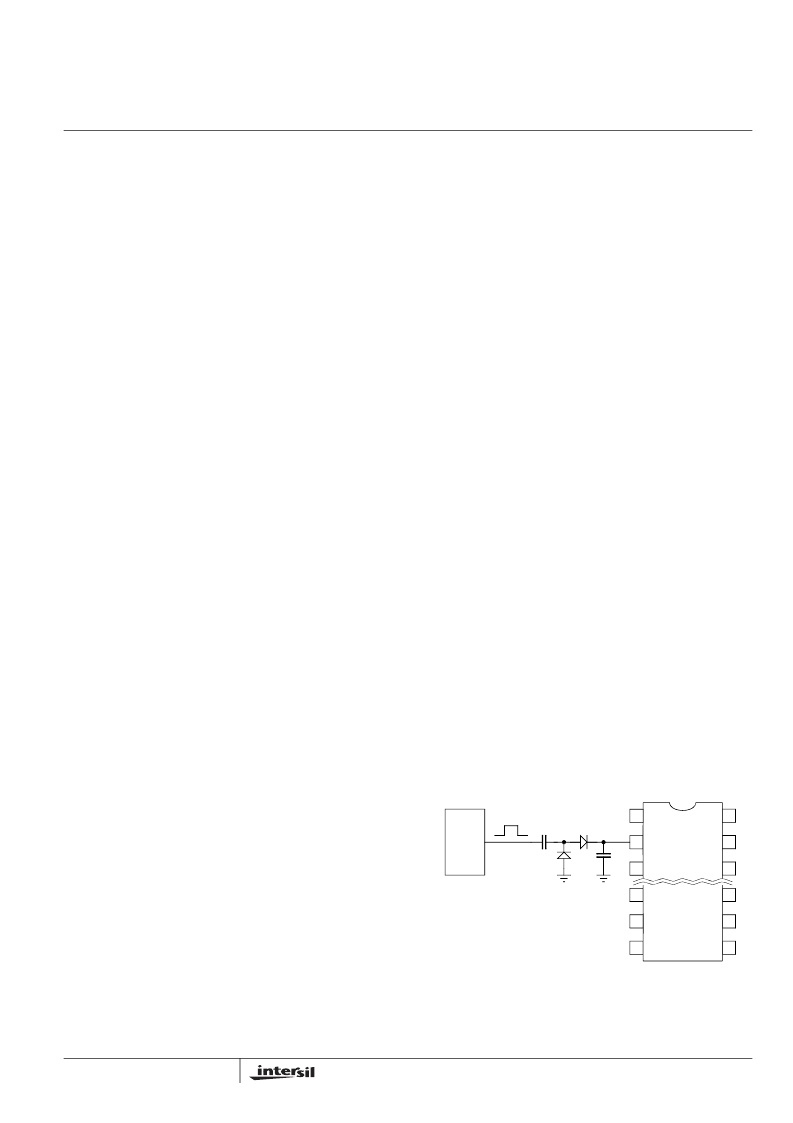
When external synchronization is required, always choose
C
OSC
such that the free-running frequency is at least 20%
lower than that of sync source to accommodate component
and temperature variations. Figure 1 shows a typical
connection.
V
OUT
0.985
1
R
2
R
1
------
+
×
=
For V
IN
= 5V
V
OUT
0.975
1
R
2
R
1
------
+
×
=
FOR V
IN
= 3.3V
FIGURE 1. OSCILLATOR SYNCHRONIZATION
2
3
11
10
9
6
7
8
15
14
EL7562
1
16
External
Oscillato
BAT54
100p
相關(guān)PDF資料 |
PDF描述 |
|---|---|
| EL7562CUZ-T13 | Monolithic 2Amp DC-DC Step-Down Regulator |
| EL7562CUZ-T7 | Monolithic 2Amp DC-DC Step-Down Regulator |
| EL7562 | Monolithic 2Amp DC-DC Step-Down Regulator(單片2A DC-DC降壓穩(wěn)壓器) |
| EL7563CM | Monolithic 4 Amp DC:DC Step-Down Regulator |
| EL7563CM-T13 | Monolithic 4 Amp DC:DC Step-Down Regulator |
相關(guān)代理商/技術(shù)參數(shù) |
參數(shù)描述 |
|---|---|
| EL7562CUZ-T13 | 功能描述:直流/直流開(kāi)關(guān)轉(zhuǎn)換器 2A DC-DC CNVRTR RoHS:否 制造商:STMicroelectronics 最大輸入電壓:4.5 V 開(kāi)關(guān)頻率:1.5 MHz 輸出電壓:4.6 V 輸出電流:250 mA 輸出端數(shù)量:2 最大工作溫度:+ 85 C 安裝風(fēng)格:SMD/SMT |
| EL7562CUZ-T7 | 功能描述:直流/直流開(kāi)關(guān)轉(zhuǎn)換器 2A DC-DC CNVRTR RoHS:否 制造商:STMicroelectronics 最大輸入電壓:4.5 V 開(kāi)關(guān)頻率:1.5 MHz 輸出電壓:4.6 V 輸出電流:250 mA 輸出端數(shù)量:2 最大工作溫度:+ 85 C 安裝風(fēng)格:SMD/SMT |
| EL7563 | 制造商:INTERSIL 制造商全稱:Intersil Corporation 功能描述:Monolithic 4 Amp DC:DC Step-Down Regulator |
| EL7563C | 制造商:ELANTEC 制造商全稱:ELANTEC 功能描述:Monolithic 4 Amp DC:DC Step-down Regulator |
| EL7563CM | 制造商:Rochester Electronics LLC 功能描述: 制造商:Intersil Corporation 功能描述: |
發(fā)布緊急采購(gòu),3分鐘左右您將得到回復(fù)。