- 您現(xiàn)在的位置:買(mǎi)賣(mài)IC網(wǎng) > PDF目錄295878 > EL7900ILCZ-T7 (INTERSIL CORP) Ambient Light Photo Detect IC PDF資料下載
參數(shù)資料
| 型號(hào): | EL7900ILCZ-T7 |
| 廠商: | INTERSIL CORP |
| 元件分類(lèi): | 模擬信號(hào)調(diào)理 |
| 英文描述: | Ambient Light Photo Detect IC |
| 中文描述: | SPECIALTY ANALOG CIRCUIT, PDSO5 |
| 封裝: | 2.10 X 2 MM, ROHS COMPLIANT, PLASTIC, ODFN-5 |
| 文件頁(yè)數(shù): | 5/8頁(yè) |
| 文件大?。?/td> | 172K |
| 代理商: | EL7900ILCZ-T7 |
5
FN7377.8
September 18, 2009
Application Information
Product Description
The EL7900 is a light-to-current optical sensor combining
photodiodes and current amplifiers on a single monolithic IC.
The photodiodes are temperature-compensated and their
spectrum resembles the human eye response. The output
current is directly proportional to the intensity of light falling
on the photodiodes. For 100lux of input fluorescent light, the
EL7900 has an output current of 60A.
The EL7900 is housed in an ultra-compact surface mount
clear plastic package.
Light-to-Current and Voltage Conversion
The EL7900 has a responsiveness that is directly
proportional to the intensity of light intercepted by the
photodiodes. Although the conversion rate varies depending
on the light sources (fluorescent light, incandescent light or
direct sunlight), in general for a fluorescent light, the light-to-
current conversion is:
Here, IOUT is the output current in A, and LINPUT is the
input light in lux.
For some applications, a load resistor is added between the
output and the ground as shown in Figure 1. The output
voltage can be expressed in Equation 2:
Here, VOUT is the output voltage and RLOAD is the value of
the load resistor added. The compliance of the EL7900's
output circuit may result in premature saturation of the
output current and voltage when an excessively large
RLOAD is used. The output compliance voltage is 300mV
below the supply voltage as listed in VO(MAX) of the
Electrical Specifications table on page 2.
In order to have the linear relationship between the input
light and the output current and voltage, a proper resistor
value (i.e., gain) should be picked for a specific input light
range. The resistor value can be picked according to
Equation 3:
Here, VSUP is the supply voltage, and LRANGE is the
specific input light range for an application. For example, an
indoor light ranges typically from 0lux to 1,000lux. A resistor
value of 4.5k
Ω for 3V supply voltage can be used. For a
small light range, a large resistor value should be used to
achieve better sensitivity; for a large light range, a small
resistor value should be used to prevent non-linear output
current and voltage.
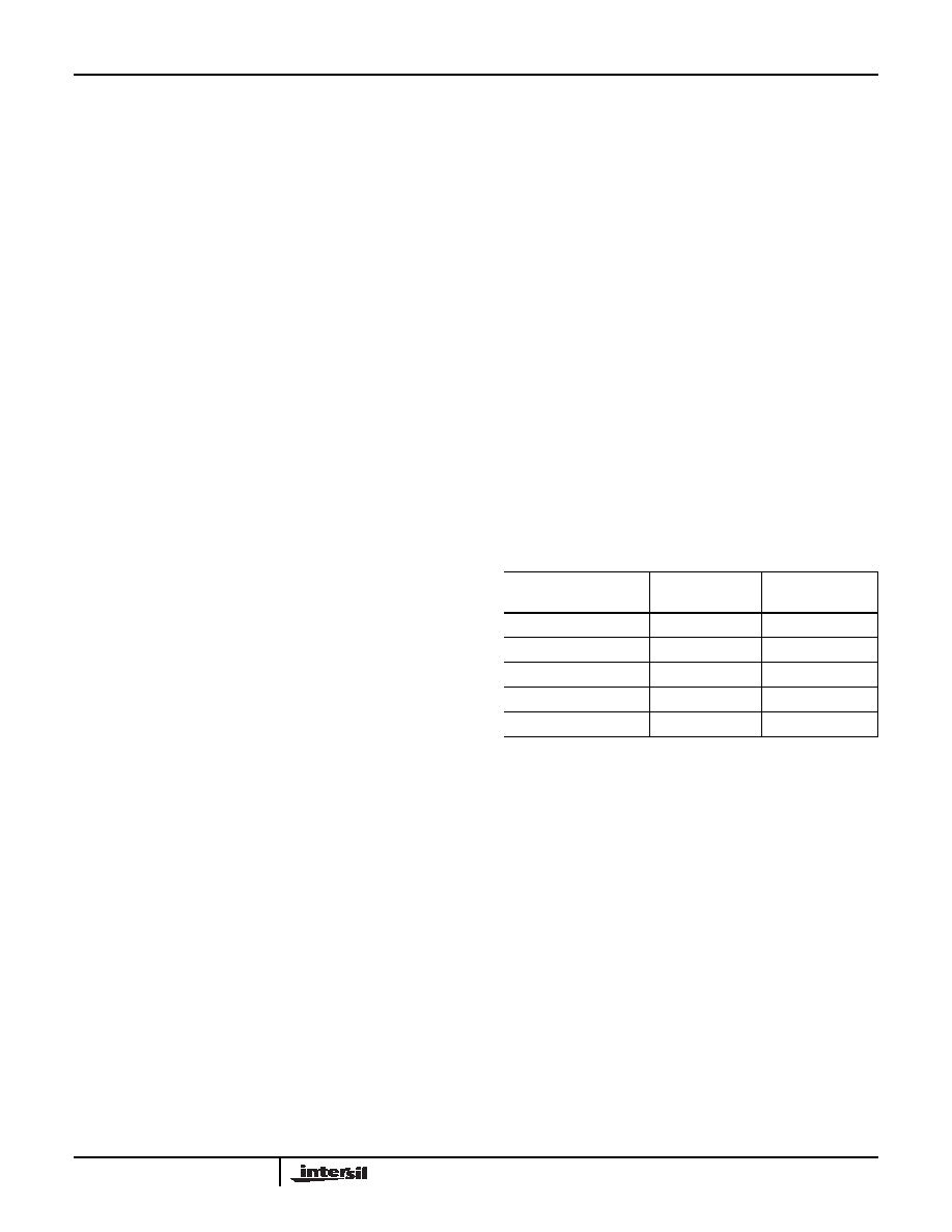
Resistor Output RLOAD Selection
The resistor output, RLOAD, determines the voltage transfer
function of the device. The device converts light into current
then RLOAD converts the output current to an output voltage.
RLOAD can range from 10Ω to 10MΩ depending on the input
lux levels. The table below lists RLOAD values to maximize
output swing for typical lux range levels. A careful balance of
dynamic swing and fast response has to be considered
when choosing RLOAD. For faster response, choose a
smaller value RLOAD to shunt stray capacitances that may
slow down response time. For maximum dynamic range or
swing, choose a higher value RLOAD. Although finite, the
output impedance of the device is considerably large.
Hence, the light-to-current conversion deviation because of
resistor loading is infinitesimal. The recommended maximum
RLOAD is 10MΩ.
The output current must never exceed 6mA. When using
load resistances less than 800
Ω, care must be taken when
lux go as high as 10,000lux because the output current rises
above 6mA before reaching the device’s output compliance.
The output compliance of the device is 300mV below the
supply. The output current stops ramping when the output
voltage reaches voltage compliance.
Application Examples
The following examples present from fully automatic to fully
manual override implementations. These guidelines are
applicable to a wide variety of potential light control
applications. The EL7900 can be used to control the
brightness input of CCFL inverters. Likewise, it can interface
well with LED drivers. In each specific application, it is
important to recognize the target environment and its
ambient light conditions. The mechanical mounting of the
sensor, light aperture hole size and use of a light pipe or
bezel are critical in determining the response of the EL7900
for a given exposure of light.
The example in Figure 10 shows a fully automatic dimming
solution with no user interaction. Choose R1 and R2 values
for any desired minimum brightness and slope. Choose C1
to adjust response time and to filter 50/60Hz room lighting.
For example, suppose you wish to generate an output
voltage from 0.25V to 1.25V to drive the input of an LED
driver controller. The 0.25V represents the minimum LED
I
OUT
60
μA
100lux
-------------------
L
INPUT
×
=
(EQ. 1)
V
OUT
I
OUT
R
LOAD
×
60
μA
100lux
-------------------
L
INPUT
R
LOAD
×
==
(EQ. 2)
R
LOAD
V
SUP
0.3V
–
()
60
μA
---------------------------------------
100lux
L
RANGE
-----------------------
×
=
(EQ. 3)
TABLE 1. VDD = 5V, MAXIMUM OUTPUT VOLTAGE = 4.7V
ILLUMINATION RANGE
(lux)
RLOAD
(k
Ω)
CURRENT OUT
(A)
0 to 10
783
0 to 6
0 to 200
39.2
0 to 120
0 to 500
15.7
0 to 300
0 to 1,000
7.8
0 to 600
0 to 10,000
0.78
0 to 6,000
EL7900
相關(guān)PDF資料 |
PDF描述 |
|---|---|
| EL8170IS | microPower, Single-Supply, CMOS Instrumentation Amplifier |
| ELEKE222JA | 1 ELEMENT, 2200 uH, GENERAL PURPOSE INDUCTOR |
| ELEKN183KA | 1 ELEMENT, 18000 uH, GENERAL PURPOSE INDUCTOR |
| ELEKE183JA | 1 ELEMENT, 18000 uH, GENERAL PURPOSE INDUCTOR |
| ELEKE182JA | 1 ELEMENT, 1800 uH, GENERAL PURPOSE INDUCTOR |
相關(guān)代理商/技術(shù)參數(shù) |
參數(shù)描述 |
|---|---|
| EL7900ILCZ-T7A | 功能描述:環(huán)境光傳感器 EL7900ILCZ AMBIENT LIGHT PHOTO DETECT RoHS:否 制造商:Vishay Semiconductors 工作電源電壓: 峰值波長(zhǎng):570 nm 最大工作溫度:+ 85 C 最小工作溫度:- 40 C 封裝 / 箱體:T-1 封裝:Bulk |
| EL8-0085 | 制造商:TE CONNECTIVITY 功能描述: |
| EL802 | 制造商:PHILIPS 制造商全稱(chēng):NXP Semiconductors 功能描述:VIDEO OUTPUT PENTODE |
| EL81 | 制造商:未知廠家 制造商全稱(chēng):未知廠家 功能描述:OUTPUT PENTODE |
| EL8100 | 制造商:INTERSIL 制造商全稱(chēng):Intersil Corporation 功能描述:200MHz Rail-to-Rail Amplifiers |
發(fā)布緊急采購(gòu),3分鐘左右您將得到回復(fù)。